
User Manual Owner's manual

2–13Installing Your Module
3"+)#!2).- %"03!04
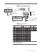
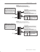
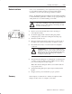
Figure 2.14
Field Wiring Arm Connection Diagram for the 1771ĆASB Series E
)-%
()%+$
)-%
. #.--%#2).-
. #.--%#2).-
. #.--%#2).-
. #.--%#2).-
. #.--%#2).-
. #.--%#2).-
. #.--%#2).-
-
%2
%1%2
1%0 13//+)%$
0!#* 0%12!02
/31("322.-
++%-50!$+%4 !"+% #!2 -. 5
+3%
()%+$
+%!0
!"+%
ATTENTION: . -.2 ,!*% #.--%#2).-1 2.
2%0,)-!+1 2(0.3'( (%1% 2%0,)-!+1
!0% #.--%#2%$ )-2%0-!++4 2. 2. !-$
2. !-$ #!--.2 "% 31%$ &.0 !-4 .2(%0
/30/.1%
%,.2% !"+%
!
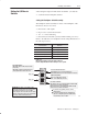
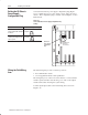
ATTENTION: Do not remove or insert the adapter
module from the I/O chassis while system power is on.
Otherwise, you may damage module circuitry.
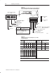
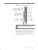
Terminals 1 and 4, 2 and 5, and 3 and 6 are internally connected on
the module. If you use these terminals (4, 5, and 6) for connection of
additional adapter modules, you disconnect the remaining adapter
modules in the series connection when you disconnect the remote
I/O adapter module wiring arm. If this is unsuitable for your
application, make your connections to terminals 1, 2, and 3 only.