
User Manual Owner's manual

2–3Installing Your Module
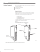
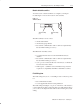
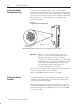
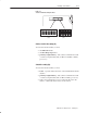
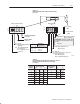
Figure 2.3
S1 and S2 Switch Assembly Locations
12345678
O
N
O
F
F
O
N
O
F
F
1234
56
OPEN
OPEN
Address Switch Assembly (S1)
You use this switch assembly to select:
• the I/O rack number
• the first I/O group number
• primary/complementary – I/O scanner communication with
or without complementary I/O (for PLC-2 and PLC-5 family
processors)
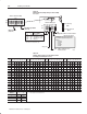
Switch Assembly (S2)
You use this switch assembly to select:
• baud – a specific baud rate based on the maximum I/O chassis
distance
• primary/complementary – I/O scanner communication with
or without complementary I/O (for PLC-2 family processors)
• scan - select whether the processor will scan all slots in the
chassis, or all but the last four slots in the chassis