!
Important User Information Because of the variety of uses for the products described in this publication, those responsible for the application and use of this control equipment must satisfy themselves that all necessary steps have been taken to assure that each application and use meets all performance and safety requirements, including any applicable laws, regulations, codes and standards.
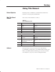
Preface Objectives Read this preface to familiarize yourself with this manual and to learn how to use it properly and efficiently. What This Manual Contains The contents of this manual are as follows: Table P.A What This Manual Contains Chapter Title What's Covered *0.+!1 &*$ 0%" ")+0" ! ,0". +!1(" "/ .& "/ #" 01."/ , &(&0&"/ *! % .!3 ." +),+*"*0/ */0 ((&*$ +1. +!1(" .+ "!1."/ *! $1&!"(&*"/ #+. &*/0 ((&*$ 0%" )+!1(" +*#&$1.&*$ +1. ")+0" .
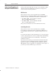
P–2 Using This Manual Understand Compliance to European Union Directives If this product has the CE mark it is approved for installation within the European Union and EEA regions. It has been designed and tested to meet the following directives.
Using This Manual Terminology Used in This Manual P–3 The following list defines common terms used in this manual. Complementary I/O: An I/O technique that allows a PC to interface with an input and output module using the same location address in different I/O chassis. Complementary Module: A module that performs an opposite function; an input module complements an output module and vice versa. Standard–Density I/O Module: A module that provides up to 8 input terminals or 8 output terminals.
P–4 Using This Manual Product Compatibility The remote I/O adapter module is one of many hardware components that make up a programmable controller system. Table P.B lists the hardware components and products with which you can use the adapter module. Table P.
Using This Manual Related Publications Read this manual in conjunction with the following documentation: Publicatin Number = Title *137* !(&22*5 (&7 23 =! "6*5 &28&0 327530 3,.; &7& .,-:&< 086 *137* 31182.(&7.32 27*5+&(* 3)80* "6*5 &28&0 53,5&11&'0* 3275300*5 5382).2, &2) $.5.2, 8.)*0.2*6 "2.9*56&0 -&66.6 53)8(7 &7& &2) 66*1'0< &2) 267&00&7.32 &28&0 53,5&11.2, &2) 4*5&7.
P–6 Using This Manual
Table of Contents Introducing the Remote I/O Adapter Module Chapter 1 Installing Your Module Chapter 2 Chapter Objectives . . . . . . . . . . . . . . . . . . . . . . . . . . . . . . . . . . . Module Description and Features . . . . . . . . . . . . . . . . . . . . . . . . . Hardware Components . . . . . . . . . . . . . . . . . . . . . . . . . . . . . . . . Diagnostic Indicators . . . . . . . . . . . . . . . . . . . . . . . . . . . . . . . . Module Switch Assemblies . . . . . . . . . . . . . . . . . . .
toc-ii Table of Contents 11(&-(-& "* 3,!$01 5(2' 91+.2 ##0$11(-& .,/+$,$-2 07 5(2' 9 +.2 ##0$11(-& .#3+$ + "$,$-2 5(2' 91+.2 ##0$11(-& (6(-& -# 9 +.2 ##0$11(-& (- -#(4(#3 + ' 11(1 ""$/2 !+$ ' 11(1 .,!(- 2(.-1 ' 11(1 # /2$0 .#3+$ .,!(- 2(.
Chapter 1 Introducing the Remote I/O Adapter Module Chapter Objectives This chapter describes the cat. no. 1771-ASB, series E remote I/O adapter module: module description and features hardware components Module Description and Features The remote I/O adapter module serves as an interface between remote I/O modules and programmable controllers. The remote I/O adapter: • transmits data up to 10,000 cable-feet (at 57.
1–2 Introducing the Remote I/O Adapter Module Hardware Components The remote I/O adapter module consists of four major components: diagnostic indicators module switch assemblies field wiring arm Diagnostic Indicators Diagnostic indicators are located on the front panel of the adapter module (Figure 1.1). They show both normal operation and error conditions in your remote I/O system.
Introducing the Remote I/O Adapter Module 1–3 Module Switch Assemblies You must set two switch assemblies to configure your adapter module. Figure 1.2 shows the location of the switches. Figure 1.
1–4 Introducing the Remote I/O Adapter Module In this chapter we discussed the functions and hardware components of the Remote I/O Adapter Module.
Chapter Chapter Objectives Module Location and Keying This chapter describes the procedures for installing your remote I/O adapter module.
2–2 Installing Your Module Setting the Module Configuration Plugs You need to set configuration plugs on the remote I/O adapter module to use 32-point I/O modules, . You access the plugs through the access hole on the left side of the module (Figure 2.2). Each plug is inserted on two pins of a three-pin connector. Thermocouple Input Modules (Cat. No. 1771-IX and -IY) are not compatible with 32-point I/O modules. Figure 2.
Installing Your Module 2–3 Figure 2.
2–4 Installing Your Module link response - unrestricted or series B emulation. Certain scanner modules with multiple communication ports require a delay in the link turnaround time to allow the central processing unit (CPU) in the scanner sufficient time to service all communication ports. Without this delay, some incoming information may be missed while the scanner is servicing another port. This results in multiple communication retries.
Installing Your Module 2–5 Figure 2.4 Module Switch Assembly Settings for PLCĆ2 Family Processors 4)2#( 11%,"+5 $$0%11 4)2#( 11%,"+5 1 2 3 4 5 6 7 8 (ON) (ON) 1 2 3 5 4 6 0%11%$ )- !2 2./ (OFF) (OFF) OPEN OPEN 0%11%$ )- !2 ".22., && Link Response 6 &.0 1%0)%1 %,3+!2). &.0 3-0%120)#2%$ ATTENTION: )-* 0%1/.-1% 14)2#( ,312 "% 4(%- 31)-' 2(% &.++.4)-' 1#!--%0 ,.
2–6 Installing Your Module Figure 2.5 Module Switch Assembly Settings for PLCĆ3 Family Processors Address Switch Assembly (S1) (ON) 1 2 3 4 5 6 7 8 (OFF) Switch Assembly (S2) OPEN 1 2 3 5 4 Pressed in at top (ON) 6 (ON) First I/O group number (Table 2.B) I/O rack number (Table 2.B) (OFF) Pressed in at bottom (OFF) OPEN Off Link Response Ć ON for series B emulation OFF for unrestricted Switch Position Maximum I/O chassis distance 1 2 ON OFF 57.6K Baud Ć 10,000ft OFF OFF 115.
Installing Your Module 2–7 Figure 2.6 Module Switch Assembly Settings for PLCĆ5 Family, SLC and ControlLogix Processors Without Complementary I/O 1 ""-#.. 1&/!% ..#) (2 2 3 4 5 6 7 8 (ON) (OFF) OPEN First I/O group number (# I/O rack number (# (ON) 1 2 1&/!% ..#) (2 3 5 4 -#..#" &* / /+, 6 (OFF) -#..#" &* / +//+) OPEN Switch Position Maximum I/O chassis distance .
2–8 Installing Your Module Figure 2.7 Module Switch Assembly Settings for PLCĆ5 Family, SLC and ControlLogix Processors With Complementary I/O ##.$// 2'0"& //$*!)3 (ON) 1 2 3 4 5 6 7 8 2'0"& //$*!)3 (OFF) OPEN 1 (ON) 2 3 5 4 .$//$# '+ 0 !,00,* OPEN I/O rack number !)$ 4 .'* .3 "& //'/ 4 ,*-)$*$+0 .3 "& //'/ %% Link Response 4 %,. /$.'$/ $*1) 0',+ %,. 1+.$/0.
Installing Your Module Setting the I/O Chassis Switches 2–9 After setting the adapter module switch assemblies, you must also • set the I/O chassis backplane switches Setting the Backplane Switch Assembly The backplane switch assembly is located on the backplane of the I/O chassis.
2–10 Installing Your Module Figure 2.9 I/O Chassis Backplane Switch Assembly Settings for Remote Adapter Module in PLCĆ3 Family Processor System O1 N O F F ATTENTION: - ,0$- # -) -# OFF *),$-$)( -) ( +"$2 ).-*.-, 0$+ -) -#$, # ,,$, 0# ( ! .&- $, - - ! ,0$- # $, , - -) -# ON *),$-$)( ).-*.-, )(( - -) -#$, # ,,$, + ' $( $( -# $+ & ,- ,- - 0# ( ! .&- ) .+, ( ' #$( ')-$)( ' 1 )(-$(. !- + ! .&- - -$)( 2 3 5 6 7 8 3 # ,,$, $( 3 %.
Installing Your Module 2–11 Figure 2.
2–12 Installing Your Module Setting the I/O Chassis Power Supply Configuration Plug You use the I/O chassis power-supply configuration plug (Figure 2.13) to identify the type of power supply you use with your remote chassis. This configuration plug is located on the backplane of series B I/O chassis. Figure 2.13 Series B I/O Chassis Power Supply Configuration Plug Settings For Use With: Set Chassis Configuration Plug to: *)/!+ ,.**&1 ') .&! %(,- &&! %( $ ,,%, 2 *),%-%)( !0-!+( & *)/!+ ,.
Installing Your Module 2–13 Figure 2.14 Field Wiring Arm Connection Diagram for the 1771ĆASB Series E +3% )-% ()%+$ %,.2% !"+% ()%+$ +%!0 !"+% )-% ++%-5 0!$+%4 !"+% #!2 -. 5 . #.--%#2). . #.--%#2).- ATTENTION: . -.2 ,!*% #.--%#2).-1 2. 2%0,)-!+1 2(0.3'( (%1% 2%0,)-!+1 !0% #.--%#2%$ )-2%0-!++4 2. 2. !-$ 2. !-$ #!--.2 "% 31%$ &.0 !-4 .2(%0 /30/.1% . #.--%#2).- . #.--%#2).- . #.--%#2).- . #.--%#2).
2–14 Installing Your Module Installing the Terminator If this is the last remote I/O adapter on the link, you must use a terminating resistor to terminate both ends of the remote I/O link (scanner end and last adapter end). Connect the terminator across terminals 1 (blue) and 3 (clear). The size of the terminator is determined by the system configuration. Older configurations use a 150 ohm resistor at both ends. With newer products that can support it, you can use an 82 ohm terminator at both ends.
Installing Your Module Module Installation 2–15 Once you’ve determined the power requirements, keying, and wiring for your adapter module, and have set the appropriate switch assemblies, you can use the following procedure to install it. Refer to the Industrial Automation Wiring and Grounding Guidelines for Noise Immunity (publication 1770-4.1) for proper grounding and wiring methods to use when installing your module.
2–16 Installing Your Module
Chapter 3 Addressing Modes for Your Remote I/O Chapter Objectives When you configure your remote I/O system, you must consider: • how to address your I/O • what combination of I/O modules and I/O chassis you can use These topics are discussed in this chapter. Hardware Addressing Programmable controllers that use the 1771-ASB remote I/O adapter module can address their I/O in 2-slot, 1-slot or 1/2 slot I/O groups.
3–2 Addressing Modes for Your Remote I/O Figure 3.1 An I/O Group Ć Up to 16 Input Terminals and 16 Output Terminals # " ! # " # " ! # " # " # " ! %! " # %! " # I/O racks are made up of I/O groups (Figure 3.1). An I/O rack is an addressing unit that can contain up to eight I/O groups. Figure 3.
Addressing Modes for Your Remote I/O 2ĆSlot Addressing 3–3 Definition: The processor addresses two I/O module slots as one I/O group. Concept: Each physical 2-slot I/O group is represented by a word in the input image table and a word in the output image table. Each input terminal corresponds to a bit in the input image table word and each output terminal corresponds to a bit in the output image table word.
3–4 Addressing Modes for Your Remote I/O Using StandardĆdensity I/O (8 point) Modules Standard-density I/O modules provide eight input terminals or eight output terminals. Figure 3.3 illustrates the 2-slot I/O group concept with two 8-point input modules. Figure 3.4 shows an 8-point input module and an 8-point output module in a 2-slot I/O group. Figure 3.
Addressing Modes for Your Remote I/O 3–5 Figure 3.
3–6 Addressing Modes for Your Remote I/O Figure 3.
Addressing Modes for Your Remote I/O 3–7 Identifying I/O Groups You identify your I/O groups in one of three ways, depending on the addressing method and I/O chassis you use. Refer to: • Figure 3.6 for 2-slot addressing when using series A I/O chassis. • Figure 3.7 for 2-slot addressing when using series B I/O chassis. • Figure 3.13 for 1-slot addressing when using series B I/O chassis. Figure 3.
3–8 Addressing Modes for Your Remote I/O Figure 3.
Addressing Modes for Your Remote I/O Complementary I/O with 2ĆSlot Addressing 3–9 Some processors support a complementary I/O configuration. Refer to the user manual for your processor to see if it supports this type of configuration. You configure complementary I/O by duplicating an I/O rack number of one I/O chassis (primary) in another I/O chassis (complementary), I/O group for I/O group.
3–10 Addressing Modes for Your Remote I/O Follow these guidelines when configuring your remote system with complementary I/O chassis: • Assign the complementary I/O rack number to a chassis of equal or smaller size than the primary chassis. • If the complementary chassis is smaller than the primary one, set the last chassis switch on the complementary chassis to the ON position, unless the adapter is in the faulted I/O search mode.
Addressing Modes for Your Remote I/O 3–11 Module Placement with 2Ćslot Addressing Figure 3.9 shows possible module placement when configuring complementary I/O with 2-slot addressing. Figure 3.9 Complementary I/O Configurations with 2Ćslot Addressing / (+ / 5 0 *- 1 ' 0 0 (0 / - 2 . 2+ !$/ - + .
3–12 Addressing Modes for Your Remote I/O • When using double-slot block-transfer modules: • The left slot of the complementary I/O group must be empty. • You can only place an 8-point output module (if any) in the right slot of the complementary I/O group. • When using single-slot block-transfer modules: • The right slot of the primary I/O group can be another single-slot block-transfer module, or an 8-point input or output module. • The left slot of the complementary I/O group must be empty.
Addressing Modes for Your Remote I/O 1ĆSlot Addressing 3–13 Definition: The processor addresses one I/O module slot as one I/O group. Concept: The physical address of each I/O group corresponds to an input and output image table word. The type of module you install (8, 16, or 32-point) determines the number of bits in these words that are used.
3–14 Addressing Modes for Your Remote I/O Thirty-two-point I/O modules need 32 input or 32 output bits in the processor’s image table. Because only 16 input and 16 output bits are available for each I/O group, to address a 32-point I/O module, the remote I/O adapter module uses the unused input or output word associated with the adjacent I/O slot. Refer to Figure 3.12.
Addressing Modes for Your Remote I/O 3–15 Identifying I/O Groups You identify your I/O groups in one of three ways, depending on the addressing method and I/O chassis you use. Refer to Figure 3.13 for 1-slot addressing when using series B I/O chassis. Figure 3.
3–16 Addressing Modes for Your Remote I/O Module Placement with 1Ćslot Addressing Figure 3.14 shows possible module placement for complementary I/O with 1-slot addressing. Figure 3.14 Complementary I/O Configurations with 1Ćslot Addressing 0 ), ! 0 5 1 +. 2 ( ! 1 1 )1 0 . 3 / 3, "%0 . , / +% , % - 2! 0 5 1 +. 2 ( ! 1 1 )1 .3"+% 1+.
Addressing Modes for Your Remote I/O 3–17 • When using double-slot block-transfer modules: – The left slot of the two corresponding I/O groups must be empty. – You can place any single-slot I/O module in the right slot of the two corresponding I/O groups. When using single-slot block-transfer modules, the corresponding I/O group must be empty.
3–18 Addressing Modes for Your Remote I/O When you select 1-slot addressing, each individual slot (one I/O group) is assigned to the corresponding word in the input or output image tables. You assign one I/O rack number to eight I/O groups (Figure 3.16). Figure 3.16 I/O Image Table and Corresponding Hardware for One Assigned Rack Number with 1Ćslot Addressing +*'+* $ # &( &* ) (&+' )" % *"&% % ! ))") ,"*! .
Addressing Modes for Your Remote I/O 1/2Ć Slot Addressing 3–19 Definition: The processor addresses one-half of an I/O module slot as one I/O group. Concept: The physical address of each I/O slot corresponds to two input and two output image table words. The type of module you install (8-, 16-, or 32-point) determines the number of bits in these words that are used.
3–20 Addressing Modes for Your Remote I/O Assigning I/O Rack Numbers with 1/2Ćslot Addressing The following rules apply when you assign I/O rack numbers for 1/2-slot addressing: • One assigned I/O rack number is made up of eight I/O groups (Figure 3.18).
Addressing Modes for Your Remote I/O 3–21 Figure 3.
3–22 Addressing Modes for Your Remote I/O Complementary I/O with 1/2ĆSlot Addressing Some processors support a complementary I/O configuration. Refer to the user’s manual for your processor to see if it supports this type of configuration. You configure complementary I/O by duplicating an I/O rack number of one I/O chassis (primary) in another I/O chassis (complementary), I/O group for I/O group.
Addressing Modes for Your Remote I/O 3–23 Follow these guidelines when you select 1/2-slot addressing: • Place input modules opposite output modules; place output modules opposite input modules. • You can use 8, 16 and 32-point I/O modules. • Output modules placed opposite output modules reflect the same bits in the output image table. You can use block-transfer modules in a complementary I/O configuration with 1/2-slot addressing.
3–24 Addressing Modes for Your Remote I/O Acceptable Chassis Combinations Not all chassis combinations are acceptable in making I/O rack number assignments. For example, a 1771-A4B I/O chassis cannot complete an assigned I/O rack number that starts in a 1771-A1 I/O chassis. Refer to Figure 3.B for acceptable beginning I/O group numbers when making your I/O rack number assignments. Table 3.
Addressing Modes for Your Remote I/O I/O Chassis/Adapter Module Combinations 3–25 Table 3.C shows the addressing methods you can achieve with the Series B chassis and the various remote I/O adapter modules. Table 3.C Series B Chassis/Adapter Module Combinations Remote I/O Adapter Module Catalog Number I/O Points Per Module 4 4 "-&". 4 "-&". *! Addressing Mode 2ĆSlot 1ĆSlot 1/2ĆSlot ". + + + + + + + ". ". + ".
3–26 Addressing Modes for Your Remote I/O
Chapter Chapter Objectives Troubleshooting With the Indicator Lights 4 In this chapter, you will learn how to use the indicators on the module frontplate for troubleshooting the module. The module has three indicators on the front plate, as shown below. Use these indicators for troubleshooting the module.
4–2 Troubleshooting Table 4.A Remote I/O System Troubleshooting Guide Indicators Active Adapter I/O Fault Rack Description Probable Cause Recommended Action On Off Off Normal indication; remote adapter is fully operational; processor is in Run mode Off On Off Adapter crash. RAM memory fault. Watchdog timeout Cycle power. Replace module if problem reoccurs. On Blink Off Module placement error I/O module in incorrect slot. Place module in correct slot in chassis.
Troubleshooting Indicators Active Adapter I/O Fault Rack Description Probable Cause 4–3 Recommended Action Blink On Off Module identification line fault Excessive noise on backplane Identify source of noise. Check power supply incoming ac power with a line disturbance analyzer. Monitor scanner channel for retries to determine if noise is entering the RIO cable. Possible problem with block transfer module. Remove to isolate.
4–4 Troubleshooting For a successful autoconfigure, insure that a processor I/O status file exists, all rack and reset and inhibit bits are zeroed, and the channel is set up for scanner, and the baud rate is correct. Make sure that: • the input and output image tables are large enough to accommodate the rack address you are attempting to assign • the adapter and chassis switches are set correctly, especially communication rate, rack and group.
Appendix A Module Location 1771 I/O chassis, leftmost slot Chassis Distance 2500 ft @ 230.4K Baud 5000 ft @ 115.2K Baud 10000 ft @ 57.6K Baud Interconnect Cable 1770-CD Power Dissipation 5 Watts Thermal Dissipation 17.06 BTU/hr Backplane Current 1.
A–2 Specifications
Appendix B Settings for 1771-AS and 1771-ASB Series A, B, C and D Remote I/O Adapters General Information Figure This appendix provides information on previous remote I/O adapters supplied by Allen–Bradley. The following table lists the adapter and respective figure reference. Description Applies to: #4'+% ' %. * $,. /#.'#/ +" /#.'#/ +" #4'+% ' %. * $,. '#)" '.'+% .* ,++#!0',+ $,. /#.'#/ +" /#.
B–2 Settings for 1771–AS and 1771–ASB Series A, B, C and D Remote I/O Adapters Figure Description Applies to: $ --%- &+' )! 0%. $ --!( '2 !..%)#- "*, !(*.! +.!, * /'! %) 3 (%'2 ,* !--*, 2-.!( -!,%!- ) $ --%- &+' )! 0%. $ --!( '2 !..%)#- "*, !(*.! +.!, * /'! %) 3 (%'2 ) *).,*' *#%1 ,* !--*, 2-.!(- %) !(*.! *)"%#/, .%*) -!,%!- ) $ --%- &+' )! 0%. $ --!( '2 !..%)#- "*, !(*.! +.
Settings for 1771–AS and 1771–ASB Series A, B, C and D Remote I/O Adapters B–3 Figure B.3 Field Wiring Arm Connection Diagram for 1771-AS, -ASB series A, B, C and D +3% )-% ()%+$ ()%+$ +%!0 !"+% )-% ++%- 0!$+%4 !"+% #!2 -. . #.--%#2). . #.--%#2).- WARNING: . -.2 ,!*% #.--%#2).-1 2. 2%0,)-!+1 2(0.3'( (%1% 2%0,)-!+1 !0% #.--%#2%$ )-2%0-!++4 2. 2. !-$ 2. !-$ #!--.2 "% 31%$ &.0 !-4 .2(%0 /30/.1% . #.--%#2).- . #.--%#2).- . #.--%#2).- . #.
B–4 Settings for 1771–AS and 1771–ASB Series A, B, C and D Remote I/O Adapters Figure B.4 Module Switch Assembly Settings for 1771-AS, -ASB series A and B Adapter for PLC-2 Family Processors Address Switch Assembly (SW-1) O N 1 2 3 4 5 6 Switch Assembly (SW-2) 7 8 O F F O N 1 2 3 Pressed in at top Closed (ON) 4 O F F First I/O group number (Table B.A) Pressed in at bottom Open (OFF) I/O rack number (Table B.
Settings for 1771–AS and 1771–ASB Series A, B, C and D Remote I/O Adapters B–5 Figure B.
B–6 Settings for 1771–AS and 1771–ASB Series A, B, C and D Remote I/O Adapters Figure B.6 Module Switch Assembly Settings for 1771-AS and 1771-ASB series A and B Adapters for PLC-3 Family Processors Address Switch Assembly (SW-1) O N 1 2 3 4 5 6 Switch Assembly (SW-2) 7 8 O F F O N 2 3 Pressed in at top Closed (ON) 4 O F F First I/O group number (Table B.C) I/O rack number (Table B.C) 1 Pressed in at bottom Open (OFF) Always OFF Maximum I/O Rack Distance ON - 10,000 cable ft. max. (57.
Settings for 1771–AS and 1771–ASB Series A, B, C and D Remote I/O Adapters B–7 Figure B.7 Module Switch Assembly Settings for 1771-ASB series C and D Adapters for PLCĆ3 Family Processors Address Switch Assembly (S1) O N 1 2 3 4 5 6 7 8 O F F Switch Assembly (S2) O N 2 3 5 4 Pressed in at bottom Open (OFF) Maximum I/O chassis distance Switch Position 1 2 ON OFF OFF OFF OFF ON ON ON Pressed in at top Closed (ON) 6 O F F First I/O group number (Table B.D) I/O rack number (Table B.
B–8 Settings for 1771–AS and 1771–ASB Series A, B, C and D Remote I/O Adapters Figure B.8 Module Switch Assembly Settings for 1771-AS and 1771-ASB series A and B Adapters for PLC-5 Family Processors without Complementary I/O Address Switch Assembly (SW-1) O N 1 2 3 4 5 6 Switch Assembly (SW-2) 7 8 O F F O N 1 2 3 Pressed in at top Closed (ON) 4 O F F Pressed in at bottom Open (OFF) First I/O group number (Table B.E) Always OFF I/O rack number (Table B.
Settings for 1771–AS and 1771–ASB Series A, B, C and D Remote I/O Adapters B–9 Figure B.9 Module Switch Assembly Settings for 1771-ASB series C and D Adapters for PLCĆ5 Family Processors Without Complementary I/O ""-#.. 1&/!% ..#) (2 O N 1 2 3 4 5 6 7 8 O F F 1&/!% ..#) (2 O N First I/O group number (# I/O rack number (# 1 2 3 5 4 -#..#" &* / /+, (+.#" 6 O F F -#..#" &* / +//+) ,#* 1&/!% +.&/&+* Maximum I/O $$ chassis distance .
B–10 Settings for 1771–AS and 1771–ASB Series A, B, C and D Remote I/O Adapters Figure B.10 Module Switch Assembly Settings for 1771-AS, -ASB series A and B Adapters for PLC-5 Family Processors with Complementary I/O Address Switch Assembly (SW-1) O N 1 2 3 4 5 6 Switch Assembly (SW-2) 7 8 O F F O N 1 2 3 Pressed in at top Closed (ON) 4 O F F First I/O group number (Table B.G) Pressed in at bottom Open (OFF) I/O rack number (Table B.
Settings for 1771–AS and 1771–ASB Series A, B, C and D Remote I/O Adapters B–11 Figure B.11 Module Switch Assembly Settings for 1771-ASB series C and D Adapters for PLCĆ5 Family Processors With Complementary I/O ##.$// 2'0"& //$*!)3 O N 1 2 3 4 5 6 7 8 2'0"& //$*!)3 O F F O N 1 2 3 5 4 6 .$//$# '+ 0 !,00,* -$+ O F F First I/O group number !)$ I/O rack number !)$ 4 .'* .3 "& //'/ 4 ,*-)$*$+0 .3 "& //'/ )2 3/ %% Link Response 4 ,+ %,.
B–12 Settings for 1771–AS and 1771–ASB Series A, B, C and D Remote I/O Adapters Figure B.12 I/O Chassis Backplane Switch Assembly Settings for 1771-AS Remote Adapter Module in PLC-2 Family Processor System $. /* Last State Switch ! & ',+(,+* ' +!"* ! **"* ) % "& "& $ *+ *+ + ! & ',+(,+* ' +!"* ! **"* ) & ) "0 .! & ,$+ "* + + O N 1 2 3 4 5 6 7 8 O F F Caution: + *."+ ! +' +! ('*"+"'& +' & ) "0 ',+(,+* .") +' +!"* ! **"* .
Settings for 1771–AS and 1771–ASB Series A, B, C and D Remote I/O Adapters B–13 Figure B.14 I/O Chassis Backplane Switch Assembly Settings for for 1771-ASB series C and D Remote Adapter Module in PLCĆ2 Family Processor System O1 N O F F 2 Last State Switch Ć # ( ).-*.-, )! -#$, # ,,$, + ' $( $( & ,- ,- - # ( ).-*.-, )! -#$, # ,,$, + ( +"$2 0# ( ! .
B–14 Settings for 1771–AS and 1771–ASB Series A, B, C and D Remote I/O Adapters Figure B.
Settings for 1771–AS and 1771–ASB Series A, B, C and D Remote I/O Adapters B–15 Figure B.
B–16 Settings for 1771–AS and 1771–ASB Series A, B, C and D Remote I/O Adapters
Appendix C Differences Between 1771ĆASB Series A, B, C, D and E Remote I/O Adapter Modules Major differences between series are noted in the table below. Table C.A Major Differences Between 1771-ASB Series Adapters 1771-ASB Series A Series B Series C Series D Series E 2,"1(-, * ' ,&$0 ,(1( * /$*$ 0$ (/+4 /$ "' ,&$ /#4 /$ ,# %(/+4 /$ "' ,&$ (/+4 /$ "' ,&$ ##$# "$/1(%(" 1(-, /#4 /$ "' ,&$ ##$# (") "$/1(%(" 1(-, $01/("1(-,0 -/ *(+(1 1(-,0 2..
C–2 Differences Between 1771-ASB Series A, B, C, D and E Remote I/O Adapter Modules
Appendix D This appendix presents some of the most commonly asked questions about application and operation of the Remote I/O Adapter Module. Questions and Answers The following questions and answers do not cover all possible questions, but are representative of the more common ones. Q. What happens to my inputs and outputs when an adapter communication failure occurs? A.
D–2 Questions and Answers Q. I just added a rack to my remote I/O network and my PLC-5 scanner channel autoconfiguration does not recognize it. Why not? A. This is typically the result of installation and configuration problems. Anything from adapter power, wiring and connections, terminations, improper setting of adapter and chassis module switches. Use the scanner and adapter status indicators as a troubleshooting tool. Easy checks include 1.
Questions and Answers D–3 Q. My remote I/O is working fine without termination resistors. Are they really required? A. Yes, termination resistors are required. Any change in the RIO network installation (i.e. cable length, baud rate) can cause a remote I/O communication failure without proper termination. Installing termination resistors reduces the chance of this occurring. Q. I have an existing PLC remote I/O system that I’m replacing with 1771.
D–4 Questions and Answers Q. How do I add a 1771-ASB adapter module to my SLC 1747-SN scanner remote I/O network? A. Enter the correct rack number, rack size and starting group in the SLC500 program I/O configuration G-file data screen. With the correct communication rate set on the scanner, download the program to the SLC processor and switch to Run mode. Communication to the adapter will commence. Q. Ever since I installed fiber optics on my remote I/O network, the adapters won’t communicate. A.
Questions and Answers D–5 ! ! ! ! ! ! # " % # $
D–6 Questions and Answers
Appendix E CSA Hazardous Location Approval CSA Hazardous Location Approval Approbation d'utilisation dans des emplacements dangereux par la CSA CSA certifies products for general use as well as for use in hazardous locations. Actual CSA certification is indicated by the product label as shown below, and not by statements in any user documentation. La CSA certifie les produits d'utilisation générale aussi bien que ceux qui s'utilisent dans des emplacements dangereux.
E–2 CSA Hazardous Location Approval
Index A !!."//&*$ /(+0 2&0% ,+&*0 )+!1("/ /(+0 /(+0 +),(")"*0 .4 1/&*$ ,+&*0 )+!1("/ 2&0% ,+&*0 )+!1("/ $.+1,/ )&3&*$ *! /(+0 !!."//&*$ % .!2 ." //&$*&*$ . ' *1) "./ 2&0% /(+0 !!."//&*$ 10+ +*#&$1." 5 5 B ',( *" /2&0 % //") (4 !"/ .&,0&+* /"00&*$/ #+. ,.+ "//+. /"00&*$/ #+. &* .")+0" +*#&$1. 0&+* /"00&*$/ #+. ,.
I–2 Index * % ## *#&+* # *+ *#&+* * %% ) $& ,# * ) (,")"% # . * )" * $,# +"&% * )" * " ) % * '+ )* *' " " +"&%* *-"+ ! ** $ #" * * ++"% *-"+ ! ** $ #. ,* +& * # + *-"+ ! ** $ #. ,* +& * # + *-"+ ! #& +"&%* *-"+ ! * ++"% * -"+! / / )" * % '+ ) , #" +"&% / ), ).
AllenĆBradley Publication Problem Report If you find a problem with our documentation, please complete and return this form. Remote I/O Adapter User Manual Pub. Name Cat. No. 1771-ASB Series E Pub. No. Check Problem(s) Type: 1771-UM001A Pub. Date February 2000 Part No.
NO POSTAGE NECESSARY IF MAILED IN THE UNITED STATES BUSINESS REPLY MAIL FIRST-CLASS MAIL PERMIT NO.
AllenĆBradley, a Rockwell Automation Business, has been helping its customers improve productivity and quality for more than 90 years. We design, manufacture and support a broad range of automation products worldwide. They include logic processors, power and motion control devices, operator interfaces, sensors and a variety of software. Rockwell is one of the world's leading technology companies. Worldwide representation.