
User Manual


Chapter
4
Publication
1771-6.5.124 – August 1997
Planning to Use Your
ControlNet Adapter Module
This chapter explains how the adapter operates on ControlNet and
provides information to assist in configuring your system. This
includes:
• overview of adapter operation
• discrete I/O data transfer
• configuring discrete I/O data transfers
• nondiscrete I/O data transfers
• using ControlNet I/O (CIO) instructions
• mapping directly into processor memory, including examples of
nondiscrete input module and output module communication
• configuring nondiscrete I/O data transfers
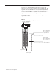
The controlling processor (network address 01) on ControlNet
contains an I/O map table. This map table stores the information
necessary for communications to be established. Each map table
entry corresponds to 1 transfer of data between the processor and an
I/O rack, or between the processor and another ControlNet processor.
The information in each map table is used to open a logical
“connection” between 2 devices.
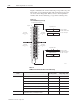
Connections are established between the processor and each adapter
to exchange input and output data on the network. Status information
is transferred along with the I/O data and is stored in a separate
status file in the specified processor. Refer to the ControlNet PLC–5
Programmable Controller (Phase 1.5) User Manual, publication
1784-6.5.22, for more on status information available.
Important: The processor compares the specified module type (in
the map table) with the device with which
communication is being attempted. Therefore, when
changing from a 1771-ACN15 to a 1771-ACNR15, or
vice versa, you must specify the new module type in the
map table.
C
ha
pt
er
Obj
ec
tiv
es
Ov
er
vi
e
w of
A
d
a
pt
er
Operation