
User Manual


3–10
Addressing Modes for Your I/O
Publication
1771-6.5.124 – August 1997
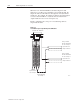
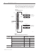
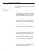
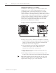
Figure 3.8 illustrates the 1/2-slot addressing concept with a 32-point
I/O module. A 32-point I/O module (with 1/2-slot I/O groups) uses
two words of the image table. When you use 8 and 16-point I/O
modules with 1/2-slot addressing, you get fewer total I/O points.
Figure 3.8
1/2-slot
Addressing Concept
Input Word 0
Output Word 0
Image Table
Words Allocated
for I/O Group 0
Input Word 1
Output Word 1
Image Table
Words Allocated
for I/O Group 1
14259
#
00
02
04
06
–
10
12
14
16
–
00
02
04
06
–
10
12
14
16
–
#
01
03
05
07
–
11
13
15
17
–
01
03
05
07
–
11
13
15
17
–
Unused
17 010 7
17 10 07
17 10 07
17 10
07
Unused
32–
p
oint
I
n
p
ut Mo
d
ul
e
1/2–slot
I/O Group
0
1/2–slot
I/O Group
0
1/2–slot
I/O Group
1
1/2–slot
I/O Group
1
Input
Input
T
able 3.C
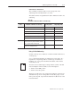
I/O Module Combinations W
ith 1/2-slot Addressing
I/O Chassis
Series
I/O Module Combinations Per I/O Group
Data Table Bits Used
Input Image Table Output Image Table
A, B 1 8-point input module 8 0
1 8-point output module 0 8
1 8-point input and output module 8 8
1 8-point input and 1 nondiscrete output module 16 8
1 nondiscrete input and 1 8-point output module 8 16
1 nondiscrete module 8 8
B or later only any mix of 8, 16 and 32-point input and output modules,
nondiscrete modules, and intelligent modules
16 16