
User Manual

Chapter
3
Publication
1771-6.5.124 – August 1997
In this chapter, you will learn:
• addressing your I/O
• using 2-slot addressing, including:
• I/O module combinations
• using standard-density I/O (8 point) modules
• using high-density (16 point) I/O modules
• using 1-slot addressing, including:
• I/O module combinations
• using 1/2- slot addressing
• addressing summary
Programmable controllers that use the ControlNet adapter module
can address their I/O in 2-slot, 1-slot or 1/2 slot I/O groups. These
three addressing methods are referred to as 2-slot addressing, 1-slot
addressing and 1/2-slot addressing.
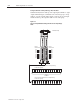
You select the addressing method with switch 5 and 6 in the I/O
chassis backplane switch assembly. You make this selection for each
chassis independently with only one method of addressing for each
chassis.
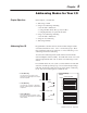
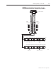
For each I/O chassis in your system, you must define how many I/O
chassis slots make up an I/O group (1 word each in the input image
table and output image table); this choice is the chassis’ addressing
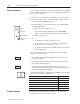
mode. Choose from among these available modes:
• 2-slot addressing
2 I/O chassis slots = 1 I/O group = 1 input
image word and 1 output image word = 16 input
bits and 16 output bits.
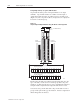
• 1-slot addressing
1
I/O chassis slot = 1 I/O group = 1 input image
word and 1 output image word = 16 input bits and
16 output bits.
• 1/2-slot addressing
1/2
of an I/O chassis slot = 1 I/O group = 1 input
image word and 1 output image word = 16 input bits
and 16 output bits.
x
x
x
x
x
x
x
x
Output Image Table
Word #
Input Image Table
Word #
16
bits input
16 bits output
16 bits input and 16 bits output
16 bits input and 16 bits output
Processor Memory
x
x
x
x
x
x
x
x
Rack #
Chapter Objectives
Addressing Your I/O