
User Manual

2–10
Installing Your ControlNet Adapter Module
Publication
1771-6.5.124 – August 1997
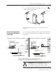
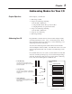
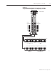
Look carefully at the status display and OK indicator when powering
up the module. These indicators provide meaningful information on
proper module operation.
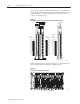
1. Apply power to the chassis – the OK indicator should not light.
2. The module runs a power on self test (POST). During this test,
the status displays 0000 through 8888.
3. If the OK indicator is red, and the display shows POST-RSET,
then POST has failed.
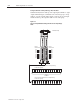
a. Press the reset pushbutton to reset.
The module reruns the POST program. If POST-RPLC
appears on the status display again, POST has failed again.
b. Replace the module.
4. If:
a. the OK indicator begins to blink green, and
b. the series/revision level of the module is displayed in the
status window (e.g. A/A, A/B, etc.), and
c. the channel A and B indicators blink alternately, the module
has passed POST.
If the indications are neither of those indicated in 3 or 4, refer to
chapter 5, “Troubleshooting.”
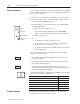
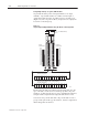
5. The module status displays INIT-A#nn (where nn is the node
number of module).
6. The channel indicators indicate network condition as shown in
the indicator table in chapter 5.
7. Then the display shows IDLE-A#nn (where nn is the node
number of module), indicating a successful configuration by the
ControlNet Configuration Manager.
For detailed information on planning and installing your ControlNet
system, see the following publications:
Publication Publication Number
ControlNet Cable System Component List AG-2.2
ControlNet Cable System Planning and Installation Manual 1786-6.2.1
ControlNet Coax Tap Installation Instructions 1786-2.3
ControlNet Network Access Cable Installation Instructions 1786-2.6
ControlNet Repeater Installation Instructions 1786-2.7
Industrial Automation Wiring and Grounding Guidelines 1770-4.1
In this chapter you learned how to install your adapter module.
Chapter 3 tells you how to address your I/O.
OK
STATUS
NET
ADDRESS
Status
OK Indicator
Reset pushbutton
Channel A and B
indicators
INIT
A#nn
IDLE
A#nn
More
Powerup Sequence
Chapter Summary