
User Manual

2–3
Installing Your ControlNet Adapter Module
Publication
1771-6.5.124 – August 1997
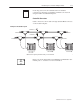
You can change the position of these bands if subsequent system
design and rewiring makes insertion of a different type of module
necessary.
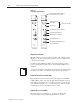
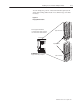
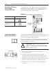
Figure 2.1
Keying
Band Positions
Upper Connector
ATTENTION: Insert or remove
keying bands with your fingers.
I/O chassis
Keying Bands
Lower Connector
11022-I
Place keying bands between:
• 54 and 56 on the upper connector
• 16 and 18 on the lower connector