
User Manual

1–4
Introducing the ControlNet Adapter Module
Publication
1771-6.5.124 – August 1997
Network Address Switch Assemblies
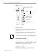
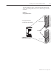
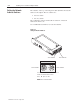
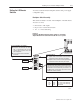
You must set two switch assemblies to configure your adapter
module with its unique network address. You access these switches
through the top of the module. Figure 1.2 shows the location of the
switches. These switches are read on powerup to establish the
network address of the module. Network address switch settings are
described in Chapter 2.
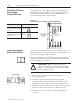
Figure 1.2
Assigning
the Network Number
Ten’s Selection
O
n
e
’s S
e
l
e
ction
Address
Switch
Assemblies
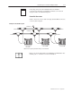
For optimum throughput, assign addresses to your ControlNet nodes
in a sequential order starting with 02. Address 01 is reserved for the
controlling processor on the network
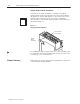
In this chapter we discussed the functions and hardware components
of the ControlNet Adapter Module.
"
Chapter Summary