Allen-Bradley ControlNet Adapter Module (Cat. No.
Important User Information Because of the variety of uses for the products described in this publication, those responsible for the application and use of this control equipment must satisfy themselves that all necessary steps have been taken to assure that each application and use meets all performance and safety requirements, including any applicable laws, regulations, codes and standards.
Preface Objectives Read this preface to familiarize yourself with this manual and to learn how to use it properly and efficiently. Audience We assume that you have previously used an Allen-Bradley programmable controller, that you are familiar with its features, and that you are familiar with the terminology we use. If not, read the user manual for your processor before reading this manual.
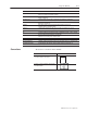
P–2 Using This Manual Terminology Used in This Manual The following list defines common terms used in this manual.
Using This Manual Use this term repeater remote I/O link RS-232-C port scheduled transfers segment serial port standard–density i/o module tap terminator trunk cable trunk-cable section two–slot addressing unscheduled transfers Conventions P–3 To describe two-port active physical-layer device that reconstructs and retransmits all traffic it hears on one segment to another segment a serial link for carrying I/O data between a PLC or SLC processor/scanner and remote I/O adapters a serial port that complie
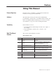
P–4 Using This Manual Product Compatibility The 1771-ACN15 and 1771-ACNR15 adapter modules are two of many hardware components that make up a programmable controller system. The table below lists the hardware components and products with which you can use the adapter module.
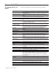
Using This Manual Related Publications Summary P–5 For additional information on planning and installing your ControlNet system, see the following publications: Publication Publication Number ControlNet PLC-5 Programmable Controllers (Phase 1.5) User Manual 1785-6.5.22 ControlNet Cable System Component List AG-2.2 ControlNet Cable System Planning and Installation Manual 1786-6.2.1 ControlNet Coax Tap Installation Instructions 1786-2.
P–6 Using This Manual Publication 1771-6.5.
Table of Contents Introducing the ControlNet Adapter Module Chapter 1 Installing Your ControlNet Adapter Module Chapter 2 Addressing Modes for Your I/O Chapter Objectives . . . . . . . . . . . . . . . . . . . . . . . . . . . . . . . . . . . Module Description and Features . . . . . . . . . . . . . . . . . . . . . . . . . Hardware Components . . . . . . . . . . . . . . . . . . . . . . . . . . . . . . . . Chapter Summary . . . . . . . . . . . . . . . . . . . . . . . . . . . . . . . . . . . .
ii Table of Contents Planning to Use Your ControlNet Adapter Module Chapter 4 Troubleshooting Chapter 5 Chapter Objectives . . . . . . . . . . . . . . . . . . . . . . . . . . . . . . . . . . . Overview of Adapter Operation . . . . . . . . . . . . . . . . . . . . . . . . . . . Discrete I/O Data Transfer . . . . . . . . . . . . . . . . . . . . . . . . . . . . . . Configuring Discrete I/O Data Transfers . . . . . . . . . . . . . . . . . . . . . Nondiscrete I/O Data Transfers . . . . . . . . . . . . . . .
Chapter 1 Introducing the ControlNet Adapter Module Chapter Objectives This chapter describes the ControlNet adapter modules’ (cat. no. 1771-ACN15 and -ACNR15): • features • hardware components, including • diagnostic indicators • communication reset pushbutton • network access port (NAP) • ControlNet connectors • network address switch assemblies Module Description and Features The 1771-ACN15 and -ACNR15 adapters control 1771 remote I/O on the ControlNet network.
1–2 Introducing the ControlNet Adapter Module Figure 1.
Introducing the ControlNet Adapter Module 1–3 monitoring devices in both redundant and non-redundant connections. Connecting programming terminals to the network using the NAP is described in Chapter 2. ControlNet Connectors Cable connection to the module is through standard BNC connectors on the module frontplate.
1–4 Introducing the ControlNet Adapter Module Network Address Switch Assemblies You must set two switch assemblies to configure your adapter module with its unique network address. You access these switches through the top of the module. Figure 1.2 shows the location of the switches. These switches are read on powerup to establish the network address of the module. Network address switch settings are described in Chapter 2. Figure 1.
Chapter 2 Chapter Objectives This chapter describes the procedures for installing your ControlNet adapter module.
2–2 Installing Your ControlNet Adapter Module For specific information required by EN 61131-2, see the appropriate sections in this publication, as well as the following Allen-Bradley publications: • Industrial Automation Wiring and Grounding Guidelines For Noise Immunity, publication 1770-4.1 • Guidelines for Handling Lithium Batteries, publication AG-5.4 • Automation Systems Catalog, publication B111 Determining Power Requirements The ControlNet adapter module requires a backplane current of 1.
Installing Your ControlNet Adapter Module 2–3 You can change the position of these bands if subsequent system design and rewiring makes insertion of a different type of module necessary. Figure 2.1 Keying Band Positions Place keying bands between: • 54 and 56 on the upper connector • 16 and 18 on the lower connector Upper Connector I/O chassis Keying Bands ATTENTION: Insert or remove keying bands with your fingers. Lower Connector 11022-I Publication 1771-6.5.
2–4 Installing Your ControlNet Adapter Module Setting the Network Address Switches The switches on the top of the adapter module determine the network address of the adapter. The two switches are: • the ten’s switch • the one’s switch The combination of these switches allows selection of network addresses from 01 to 99. Use a small bladed screwdriver to rotate the switches. Figure 2.
Installing Your ControlNet Adapter Module Setting the I/O Chassis Switches 2–5 You must set the I/O chassis backplane switches and power-supply configuration plug. Backplane Switch Assembly This switch assembly is located on the backplane of the I/O chassis. You use it to select: • the last state of all outputs • the processor restart lockout feature • 1/2-, 1- or 2-slot addressing Figure 2.
2–6 Installing Your ControlNet Adapter Module Setting the I/O Chassis Power Supply Configuration Plug Set the I/O chassis power-supply configuration plug (Figure 2.4) to identify the type of power supply you are using with your remote chassis. This configuration plug is located on the backplane of 1771-A1B through -A4B or later I/O chassis. Figure 2.
Installing Your ControlNet Adapter Module ! 2–7 ATTENTION: Do not force the module into the backplane connector. If you cannot seat the module with firm pressure, check the alignment and keying. Forcing the module can damage the backplane connector or the module. 5. Snap the chassis locking bar (or locking latch on earlier chassis) over the top of the module to secure it. Make sure the locking pins on the locking bar are fully engaged.
2–8 Installing Your ControlNet Adapter Module ATTENTION: Do not allow any metal portions of the tap to contact any conductive material. If you disconnect the tap from the adapter, place the dust cap back on the straight or right angle connector to prevent the connector from accidentally contacting a metallic grounded surface. ! segment 1 tap dust cap 20093-I 2. Remove and discard the dust caps from the adapter BNC jacks. 3.
Installing Your ControlNet Adapter Module 2–9 5. Connect this tap’s straight or right angle connector to the B BNC connector on the adapter. segment 2 segment 1 tap tap 20093-I After terminating your segments, you connect your node to the network. Connecting Programming Terminals to the Network via the NAP You can connect programming terminals to the ControlNet network by connecting to the network access port (NAP). Two methods are shown below.
2–10 Installing Your ControlNet Adapter Module Powerup Sequence Look carefully at the status display and OK indicator when powering up the module. These indicators provide meaningful information on proper module operation. 1. Apply power to the chassis – the OK indicator should not light. 2. The module runs a power on self test (POST). During this test, the status displays 0000 through 8888. 3. If the OK indicator is red, and the display shows POST-RSET, then POST has failed. NET ADDRESS Status a.
Chapter Chapter Objectives 3 In this chapter, you will learn: • addressing your I/O • using 2-slot addressing, including: • I/O module combinations • using standard-density I/O (8 point) modules • using high-density (16 point) I/O modules • using 1-slot addressing, including: • I/O module combinations • using 1/2- slot addressing • addressing summary Addressing Your I/O Programmable controllers that use the ControlNet adapter module can address their I/O in 2-slot, 1-slot or
3–2 Addressing Modes for Your I/O I/O groups are made up of I/O terminals (Figure 3.1). An I/O group is an addressing unit that can contain up to 16 input terminals and 16 output terminals. You select an I/O chassis to have either 2-slot, 1-slot or 1/2-slot I/O groups. Figure 3.
Addressing Modes for Your I/O 3–3 Using 2-Slot Addressing Definition: The processor addresses two I/O module slots as one I/O group. Concept: Each physical 2-slot I/O group is represented by a word in the input image table and a word in the output image table. Each input terminal corresponds to a bit in the input image table word and each output terminal corresponds to a bit in the output image table word.
3–4 Addressing Modes for Your I/O Using Standard-density I/O (8 point) Modules Standard-density I/O modules provide eight input terminals or eight output terminals. Figure 3.3 illustrates the 2-slot I/O group concept with two 8-point input modules. Figure 3.4 shows an 8-point input module and an 8-point output module in a 2-slot I/O group. Figure 3.
Addressing Modes for Your I/O 3–5 Figure 3.4 8-point Input and Output Modules Using Eight Bits of the Input Image Table Word and Eight Bits of the Output Image Table Word 2-slot I/O Group Input T erm inals 00 01 02 03 04 05 06 07 O utput T erm inals 10 11 12 13 14 15 16 17 O utput im age table w ord corresponding to the I/O group. 17 16 15 14 13 12 11 10 07 06 05 04 03 02 01 00 O utput bits used unused Input im age table w ord corresponding to the I/O group.
3–6 Addressing Modes for Your I/O Using High-density (16 point) I/O Modules 16-point I/O modules provide 16 input terminals or 16 output terminals. 16-point I/O modules use a full word in the input or output image table when they are addressed as a 2-slot I/O group (Figure 3.5). Two 16-point modules (one input and one output) can be used in a 2-slot I/O group. Figure 3.
Addressing Modes for Your I/O 3–7 Using 1-Slot Addressing Definition: The processor addresses one I/O module slot as one I/O group. Concept: The physical address of each I/O group corresponds to an input and output image table word. The type of module you install (8, 16, or 32-point) determines the number of bits in these words that are used.
3–8 Addressing Modes for Your I/O When the 1771-ACN15/ACNR15 ControlNet adapter module addresses a 1-slot I/O group containing a 32-point I/O module, the adapter module uses the unused word assigned to the adjacent I/O module slot. For example, the adapter module uses the unused input word associated with I/O slot 1 (because that slot must hold an output module and does not use its input word). Figure 3.7 illustrates the concept of 1-slot addressing with two 32-point I/O modules. Figure 3.
Addressing Modes for Your I/O 3–9 I/O Module Combinations The combination of I/O modules you can use depends on the addressing method and I/O chassis you select. The table below lists acceptable I/O module combinations with 1-slot addressing. Table 3.
3–10 Addressing Modes for Your I/O Figure 3.8 illustrates the 1/2-slot addressing concept with a 32-point I/O module. A 32-point I/O module (with 1/2-slot I/O groups) uses two words of the image table. When you use 8 and 16-point I/O modules with 1/2-slot addressing, you get fewer total I/O points. Figure 3.
Addressing Modes for Your I/O Addressing Summary Use this table as a quick reference for addressing.
3–12 Addressing Modes for Your I/O Publication 1771-6.5.
Chapter 4 Planning to Use Your ControlNet Adapter Module Chapter Objectives This chapter explains how the adapter operates on ControlNet and provides information to assist in configuring your system.
4–2 Planning to Use Your ControlNet Adapter Module Discrete I/O Data Transfer All 1771 discrete I/O data is mapped into the processor’s I/O image table according to the user-configurable I/O map table stored in the processor. This image table location is specified on the ControlNet configuration screen. Configuring Discrete I/O Data Transfers ControlNet provides significant flexibility when configuring discrete I/O data transfers.
Planning to Use Your ControlNet Adapter Module 4–3 • The number of input words and output words do not have be the More Nondiscrete I/O Data Transfers same for an adapter. • Update times (Expected Network Packet Times) are not required to be the same for all remote racks in the system. Update times can be selected based on your application requirements. Refer to the PLC-5 ControlNet programmable controller manual or 6200 Software manuals for more information on the ControlNet configuration screens.
4–4 Planning to Use Your ControlNet Adapter Module Mapping Directly Into Processor Memory ControlNet also allows mapping 1771 nondiscrete I/O modules directly into processor memory. This eliminates the need for programming CIO or other transfer instructions in your ladder program. When you map a nondiscrete I/O module, the processor opens a connection to the adapter. Data is produced and/or consumed over the network, continuously and asynchronous to the ladder logic program scan.
Planning to Use Your ControlNet Adapter Module 4–5 Example: Nondiscrete Output Module Communications 0 1 2 3 4 5 6 7 3 1771-OFE Empty 1771-P4S 2 1771 8 Point In PLC-5/40C 1 0 1 2 3 4 5 6 7 Nondiscrete Output Module 1. The processor opens a connection to the adapter for producing the data for the nondiscrete module. 2. The processor produces the most recent copy of the designated data table value you specified in your configuration onto the network at the Actual Network Packet Time. 3.
4–6 Planning to Use Your ControlNet Adapter Module Configuring Nondiscrete I/O Data Transfers The following are important factors to consider when planning and configuring nondiscrete I/O modules: • You can communicate with nondiscrete I/O modules anywhere in the rack, including slots that are not mapped into the discrete I/O image files. Note that nondiscrete I/O modules can be placed so no I/O image space is used.
Chapter 5 Chapter Objectives In this chapter, you will learn how to use the indicators on the module frontplate for troubleshooting the module. This includes: • troubleshooting with the status indicators and status display, including: • OK indicator and display mnemonics • ControlNet status indicators Troubleshooting With the Status Indicators and Status Display The module has indicators on the front plate, as shown below.
5–2 OK Indicator and Display Mnemonics OK Indicator OK Red/ Green Display Mnemonic NET T ADDRESS A SS Descr Description n Pr a le Cause Probable ause Rec Recommended en e Ac Actionn STATUS Off Off Power supply fault Check power supply, cable connectors, and seat adapter firmly in chassis. Defective adapter Contact Allen-Bradley service. Adapter is running Power On Self Test None None CODE UPDT Firmware update mode. Adapter firmware is being updated via A-B Flash Update Utility.
5–3 OK Indicator OK Red/ Green Display Mnemonic NET ADDRESS Description Probable Cause Recommended Action STATUS Green Blinking alternately red and green RUN Normal indication – processor is in RUN mode. None None PRGM Normal indication – processor is in program or test mode. None None BOOT Running boot code. Adapter has corrupted firmware. Update adapter firmware with A-B Flash Update Utility. ControlNet Status Indicators • steady – indicator is on continuously in the defined state.
5–4 Publication 1771-6.5.
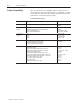
Module Location 1771 I/O chassis, leftmost slot Interconnect Cable Quad shield RG-6 coaxial cable – Refer to the ControlNet Cable System manual (pub. no. 1786-6.2.1) for more information Power Dissipation 5 Watts Thermal Dissipation 17.06 BTU/hr Backplane Current 1.
A–2 Specifications Publication 1771-6.5.
Index A addresses, assigned, 1–4 addressing 1–slot, 3–7 with 32–point modules, 3–8 1/2–slot, 3–9 2–slot, 3–3 using 16–point modules, 3–6 with 8–point modules, 3–4 guidelines for selecting addressing modes, 3–11 I/O groups, 3–2 addressing hardware, 3–1 nondiscrete I/O, 4–3 diagnostic indicators, 1–2 alphanumeric display, 1–2 OK, 1–2 display mnemonics, 5–2 E EMC directive, 2–1 European directives, compliance to, 2–1 F factors to consider, 4–2 B backplane current, 2–2 backplane switch assembly description
I–2 Index L low voltage directive, 2–1 P position, keying bands, 2–3 power requirements, 2–2 M module installation, 2–6 powerup sequence, 2–10 programming terminal, connecting to network, 2–9 module location, 2–2 module switches, setting, 2–4 N network access port, 1–2 R racks, I/O, 3–2 redundant system, example of, 1–3 reset pushbutton, 1–2 network address, switches, 2–4 network addresses, acceptable, 2–4 network connections, using taps, 2–7 network number, assigning, 2–4 status display indicator
Allen-Bradley Publication Problem Report If you find a problem with our documentation, please complete and return this form. Pub. Name ControlNet Adapter Module User Manual Cat. No. 1771-ACN15, -ACNR15 Pub. No. Check Problem(s) Type: 1771-6.5.124 Pub. Date August 1997 Part No.
PLEASE FASTEN HERE (DO NOT STAPLE) PLEASE FOLD HERE NO POSTAGE NECESSARY IF MAILED IN THE UNITED STATES BUSINESS REPLY MAIL FIRST-CLASS MAIL PERMIT NO.
Support Services At Allen-Bradley, customer service means experienced representatives at Customer Support Centers in key cities throughout the world for sales service and support.
Allen-Bradley, a Rockwell Automation Business, has been helping its customers improve productivity and quality for more than 90 years. We design, manufacture and support a broad range of automation products worldwide. They include logic processors, power and motion control devices, operator interfaces, sensors and a variety of software. Rockwell is one of the world’s leading technology companies. Worldwide representation.