Application Data Industrial Automation Wiring and Grounding Guidelines Purpose This publication gives you general guidelines for installing an Allen-Bradley industrial automation system that may include programmable controllers, industrial computers, operator-interface terminals, display devices, and communication networks. While these guidelines apply to the majority of installations, certain electrically harsh environments may require additional precautions.
Industrial Automation Wiring and Grounding Guidelines Raceway Layout Considerations The raceway layout of a system is reflective of where the different types of I/O modules are placed in I/O chassis. Therefore, you should determine I/O-module placement prior to any layout and routing of wires. However, when planning your I/O-module placement, segregate the modules based upon the conductor categories published for each I/O module so that you can follow these guidelines.
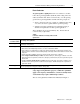
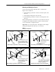
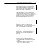
Industrial Automation Wiring and Grounding Guidelines 3 Route Conductors To guard against coupling noise from one conductor to another, follow these general guidelines (Table B) when routing wires and cables (both inside and outside of an enclosure).
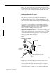
Industrial Automation Wiring and Grounding Guidelines Figure 1 Mounting Assembly Details Category-2 Conductors Category-1 Conductors (ac Power Lines) Conduit Tighter spacing allowed with conduit Conduit Enclosure Wall Use greater spacing without conduit Transformer Tighter spacing allowed where forced by spacing of connection points Category-2 Conductors I/O Block 1771 I/O Chassis Place modules to comply with spacing guidelines if possible Mounting, Bonding, and Grounding Publication 1770-4
Industrial Automation Wiring and Grounding Guidelines 5 Mounting and Bonding the Chassis You can mount the chassis with either bolts or welded studs.
Industrial Automation Wiring and Grounding Guidelines Make good electrical connection between each chassis, back-panel, and enclosure through each mounting bolt or stud. Wherever contact is made, remove paint or other non-conductive finish from around studs or tapped holes. Bonding and Grounding the Chassis With solid-state controls, proper bonding and grounding helps reduce the effects of emi and ground noise.
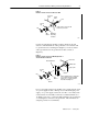
Industrial Automation Wiring and Grounding Guidelines 7 Figure 4 Details of Ground Connection at Enclosure Wall Enclosure Wall Scrape Paint Bolt Ground Lug Scrape paint on enclosure wall and use a star washer. Nut Star EquipmentWasher Grounding Conductor 10020 Connect an equipment grounding conductor directly from each chassis to an individual bolt on the ground bus. For a chassis with no ground stud, use a mounting bolt (Figure 5).
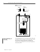
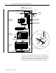
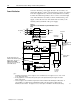
Industrial Automation Wiring and Grounding Guidelines Figure 6 Typical Grounding Configuration Enclosure Wall See Figure 3 See Figure 4 Ground Bus Groundingelectrode Conductor To Groundingelectrode System 1756 Chassis with 1756-PA72 Power Supply Equipment-grounding Conductors 8AWG Equipment-grounding Conductors 14AWG FLEX I/O Modules DIN Rail 1771-P7 Power Supply 1771 Chassis with 1771-P7 Power Supply I/O Chassis Wall 14 AWG Mini-processor with built-in power supply Ground Lug Nut Power-sup
Industrial Automation Wiring and Grounding Guidelines 9 Some products have no visible groundable chassis and no ground lug or ground terminal, but mount on a DIN rail. The FLEX I/O products are in this category. The chassis of these products are grounded only thru the DIN rail. For these products, connect an equipment-grounding conductor directly from the mounting bolt on the DIN rail to an individual bolt on the ground bus.
Industrial Automation Wiring and Grounding Guidelines You can connect the power supply directly to the secondary of a transformer (Figures 7 and 8). The transformer provides dc isolation from other equipment not connected to that transformer secondary. Connect the transformer primary to the ac source; connect the high side of the transformer secondary to the L1 terminal of the power supply; connect the low side of the transformer secondary to the neutral (common) terminal of the power supply.
Industrial Automation Wiring and Grounding Guidelines 11 Connect one input directly to the L1 side of the line, on the load side of the CRM contacts, to detect whether the CRM contacts are closed. In the ladder logic, use this input to hold off all outputs anytime the CRM contacts are open. (Refer to your programming manual.) If you fail to do this, closing the CRM contacts could generate transient emi because outputs are already turned on.
Industrial Automation Wiring and Grounding Guidelines Common Power Source for I/O Unless each I/O of a module or block is individually isolated, multiple I/O within the block or module share a common terminal for one side of the power source. All I/O sharing a common terminal must share a common power source (i.e., from the same pole of a disconnect or from the same transformer tap). If a module or block has multiple commons, each common and its I/O may be isolated from the other commons.
Industrial Automation Wiring and Grounding Guidelines 13 For example, the external-transformer load of a 1771-P4S power-supply module at maximum backplane load current is 140VA (2.5 x 56W = 140). A 140VA transformer could be used if a 1771-P4S power-supply module were the only load. A 500VA transformer should be used if there were 360VA of load in addition to that of the 1771-P4S power-supply module.
Industrial Automation Wiring and Grounding Guidelines Isolation Transformer — For applications near excessive electrical noise generators, an isolation transformer (for the second transformer) provides further suppression of electromagnetic interference from other equipment. The output actuators being controlled should draw power from the same ac source as the isolation transformer, but not from the secondary of the isolation transformer (Figure 9).
Industrial Automation Wiring and Grounding Guidelines Surge-Suppression 15 Transient emi can be generated whenever inductive loads such as relays, solenoids, motor starters, or motors are operated by “hard contacts” such as pushbutton or selector switches. The wiring guidelines are based on the assumption that you guard your system against the effects of transient emi by using surge-suppressors to suppress transient emi at its source.
Industrial Automation Wiring and Grounding Guidelines Figure 10 Examples of where to use Suppression 1MS L2 L1 1MS 1MS solid-state switch L2 1MS Although the motor starter is an inductive load, it does not need a suppressor because it is switched by a solid-state device. ac output module L1 L2 1M suppressor The motor needs supressors because it is an inductive load switched by hard contacts.
Industrial Automation Wiring and Grounding Guidelines 17 Figure 11 Typical Suppression Applications 230/460V ac Electrocube 1676-13 120V ac 3-Phase Motor Cat. No. 700-N24 For small apparatus (relays, solenoids, and motor starters up to size 1) For 3-phase apparatus, a suppressor is needed across each phase + 120/240V ac – V dc Cat. No.
Industrial Automation Wiring and Grounding Guidelines Surge-suppressors are usually most effective when connected at the inductive loads. They are still usable when connected at the switching devices; however, this may be less effective because the wires connecting the switching devices to the inductive loads act as antennas that radiate emi. You can see the effectiveness of a particular suppressor by using an oscilloscope to observe the voltage waveform on the line.
Industrial Automation Wiring and Grounding Guidelines Avoiding Unintentional Momentary Turn-on of Outputs 19 Unintentional turn-on of outputs as the power source is connected or disconnected, even if momentary, can result in injury to personnel as well as damage to equipment. The danger is greater with fast-response actuators.
Industrial Automation Wiring and Grounding Guidelines • National Electrical Code (ANSI/NFPA 70) — Article 250 of • • • • • • this code provides information about the types and sizes of conductors and methods for safely grounding electrical equipment and components. Articles 725-5, 725-15, 725-52, and 800-52 restrict the placement of different types of conductors in a composite cable, a raceway, or a cable tray.