
Manual

Chapter 4
C
Communicating with the Smart
Transmitter Interface
4-33
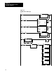
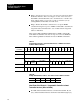
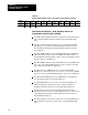
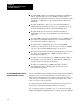
Table 4.R
Smart
Transmitter Interface to Programmable Controller BTR Data Long Frame
Format for Response to HART Command 1
Octal Bits 17 16 15 14 13 12 11 10 07 06 05 04 03 02 01 00
Decimal Bits 15 14 13 12 11 10 09 08 07 06 05 04 03 02 01 00
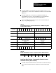
Word
00
Smart Transmitter Interface Channel Number Smart Transmitter Interface Command
Word
01
Smart Transmitter Interface Status Smart Transmitter Interface Error Code
Word
02
HART Address HART Delimiter
Mas
Adr
Bur
Mde
Manufacturer
Identification Code
Lng
Frm
0 0 0 0
Frame Type
Word
03
Device ID
(Most Significant Byte)
Manufacturer's
Device Type
Word
04
Device ID
(Least Significant Byte)
Device ID
(Middle Byte)
Word
05
Byte Count HART Command
Word
06
HART Response Code
Second Byte First Byte
Word
07
Primary Variable
(Most Significant Byte)
Primary Variable
Units
Word
08
Primary Variable
(3rd Most Significant Byte)
Primary Variable
(2nd Most Significant Byte)
Word
09
Check Byte Primary Variable
(Least Significant Byte)
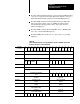
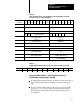
Table 4.S
Example
BTR Data Offset at D9:40 Long Frame Format for HART 1 Command
Address 0 1 2 3 4 5 6 7 8 9
D9:40 0110 8000 A686 000D 1115 0701 0000 4220 3991 B356
Long Frame Word Contents Smart Transmitter Interface to
Programmable Controller (Offset at D9:40)
Word 00: Smart Transmitter Interface Command is hexadecimal 10 (low
byte); Smart Transmitter Interface Channel is hexadecimal 01 (high
byte).
Word 01: Smart Transmitter Interface Error Code is hexadecimal 00
indicating no errors (low byte); Smart Transmitter Interface Status is
hexadecimal 80 indicating the Smart Transmitter Interface has been
reset (high byte).