
Manual

Communicating with the Smart
Transmitter Interface
Chapter 4
Communicating with the Smart Transmitter
Interface
4-28
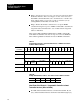
Rung 4: Sets B3:1 if a non-zero error code was received from the Smart
Transmitter Interface. This forces rung 0 to be true on the next scan so
that HART command #0 will be sent to the field device. A check is also
made on B3:6 which you can set if you wish to restart the cycle by
sending HART command #0 to the field device.
Rung 5: Checks that all data is valid and if so sets up the HART
command #1 using the response to HART command #0 to determine the
long frame address. Bit B3:0 is also set to indicate that the long frame
address is initialized.
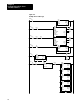
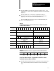
Table 4.L and Table 4.M illustrate BTW data for HART command #0,
while Table 4.N and Table 4.O show the response received as BTR data.
Table 4.P through Table 4.S illustrate the data for HART command #1.
Table 4.L
Programmable
Controller to Smart T
ransmitter Interface BTW Data Short Frame
Format for HART Command 0
Octal Bits 17 16 15 14 13 12 11 10 07 06 05 04 03 02 01 00
Decimal Bits 15 14 13 12 11 10 09 08 07 06 05 04 03 02 01 00
Word
00
Smart Transmitter Interface Channel Number Smart Transmitter Interface Command
Word
01
Smart Transmitter Interface Parameter Smart Transmitter Interface Control
Word
02
HART Address HART Delimiter
Mas
Adr
0 Logical
Address
Slave Address Lng
Frm
0 0 0 0 Frame Type
Word
03
Byte Count HART Command
Word
04
0 0 0 0 0 0 0 0 Check Byte
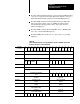
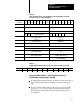
Table 4.M
Example
BTW Data Offset at D9:00 Short Frame Format for HART Command 0
Address 0 1 2 3 4
D9:00 0110 0000 8002 0000 0000
Short Frame Word Contents Programmable Controller to Smart
Transmitter Interface (Offset at D9:00)
Word 00: Smart Transmitter Interface command hexadecimal 10 (low
byte); Smart Transmitter Interface channel hexadecimal 01 (high byte).