
Manual

Chapter 4
C
Communicating with the Smart
Transmitter Interface
4-25
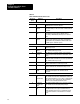
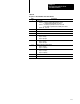
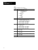
Table 4.J
Response
to Read ID Command
Data Byte description Status reply
1 Mode/Status Byte 00 (No Modes)
2 Interface/Processor Type EE (Extended)
3 Extended Interface Type 34 DF1 on RS232 in Full Duplex mode
36 DF1 on RS232 in Half Duplex mode
4 Extended Processor Type 57
5 Series/Revision
Bits 04:
Bits 57:
0 = Revision A
1 = Revision B, etc.
0 = Series A
1 = Series B, etc.
6 16 Bulletin Name (in ASCII) "1770HT1 "
17 24 Reserved 0
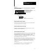
Programmable Logic Controllers communicate with HART field devices
using block transfers over the RIO link to the Smart Transmitter Interface.
Commands are sent in the form of a Block Transfer Write (BTW), while
responses are received via a Block Transfer Read (BTR).
The Smart Transmitter Interface expects BTWs and BTRs in pairs with the
BTW preceding the BTR. If the Smart Transmitter Interface receives a
BTR without a preceding BTW, it will return a Smart Transmitter Interface
Error Code hexadecimal 02 (see Table 4.F). The one exception occurs
when the programmable controller specifically indicates that no response is
required. To do this, set bit 6 of the Smart Transmitter Interface Control
byte (see Figure 4.8). In this case, the next transfer should be another
BTW.
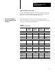
You must program the programmable controller to execute the BTW and
BTR instructions to transfer data between the programmable controller and
the HART field device. You can fix both the BTW and BTR data file
lengths at the largest values required by your application because the Smart
Transmitter Interface does not interpret extra BTW data and pads out BTR
data blocks with zeros. Figure 4.10 and Table 4.K show an example PLC-5
ladder logic program with its required data files.
Programmable Controller
Communication with HART
Field Devices