
Manual

Communicating with the Smart
Transmitter Interface
Chapter 4
Communicating with the Smart Transmitter
Interface
4-24
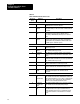
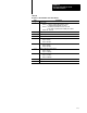
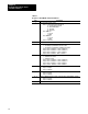
Table 4.I
Response
to Read Module Status and Statistics
Byte Description
1 Smart Transmitter Interface Status
Bits 0,1 Smart Transmitter Interface Mode
00 = Poll and Response Mode
01 = Burst Monitor Mode
10 Reserved
11 = Reserved
Bit 2 RAM Test
0 = passed
1 = failed
Bit 3 ROM Test
0 = passed
1 = failed
Bits 47 Reserved
2 Reserved
3, 4, 5, 6 Device communication status with 1 bit per channel
0 = last attempt to poll field device was successful
1 = last attempt to poll field device including retries failed
Byte 3 Bit #7 = Channel 32 ... Bit #0 = Channel 25
Byte 4 Bit #7 = Channel 24 ... Bit #0 = Channel 17
Byte 5 Bit #7 = Channel 16 ... Bit #0 = Channel 9
Byte 6 Bit #7 = Channel 8 ... Bit #0 = Channel 1
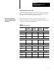
7, 8, 9, 10 Channel in Burst Monitor Mode scan list with 1 bit per channel
0 = channel not in scan list
1 = channel in scan list
Byte 7 Bit #7 = Channel 32 ... Bit #0 = Channel 25
Byte 8 Bit #7 = Channel 24 ... Bit #0 = Channel 17
Byte 9 Bit #7 = Channel 16 ... Bit #0 = Channel 9
Byte 10 Bit #7 = Channel 8 ... Bit #0 = Channel 1
11, 12 Number of BTW requests received on RIO link
Byte 11 low byte
Byte 12 high byte
13, 14 Number of BTW data blocks received from programmable controller
Byte 13 low byte
Byte 14 high byte
15, 16 Number of BTW data blocks received via passthrough of programmable controller
Byte 15 low byte
Byte 16 high byte
17 42 Reserved