
Manual

Installing the Smart Transmitter Interface
Products
Chapter 2
2-27
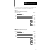
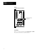
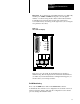
If your computer requires active DSR and CTS signals, add jumpers to the
computer connections as shown in Figure 2.23 and Figure 2.24.
Figure 2.23
Jumper
Positions for DSR and CTS Lines (25 pin)
1
TXD 2
RXD 3
GND 7
Computer
3 RXD
2 TXD
7 GND
4 RTS
5 CTS
6 DSR
8 DCD
20 DTR
Shield
90007
Communications Controller
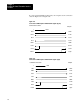
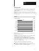
Figure 2.24
Jumper
Positions for DSR and CTS Lines (9 pin)
1
TXD 2
RXD 3
GND 7
Computer
2 RXD
3 TXD
5 GND
7 RTS
8 CTS
6 DSR
1 DCD
4 DTR
Shield
90008
Communications Controller