
Manual
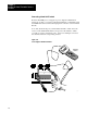

Installing the Smart Transmitter Interface
Products
Chapter 2
2-24
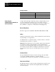
Activity Indicator
If the RIO LED is: The RIO link is:
Off Inactive
On Active, normal communication is in progress
Flickering Communications established, but not active
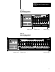
A single, full or half duplex, RS-232C serial port using the DF1 protocol
provides communications with the host processor. This connector is
located at the left end of the Communications Controller (see Figure 1.1).
The 1770-HT1 is configured as a DTE (Data Terminal Equipment).
RS232C Baud Rates
Baud rates supported are 300, 600, 1200, 2400, 4800, 9600 and 19200.
Cables
Cabling for the RS-232C connector of the Communications Controller will
vary depending on your application.
Use Belden #8723 (or equivalent) cable to construct a cable to connect the
Communications Controller to a computer.
Important: The length must not exceed 50 feet, and the cable shield must
be connected to chassis ground (using Pin 1) at the Communications
Controller end only. If the length required exceeds 50 feet, a modem or line
driver must be used. In addition, if multiple Communications Controllers
are connected to the host processor modems must be used to isolate the
signals.
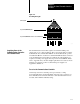
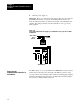
Activity Indicator
The green LED RS-232 indicator, located to the upper left of the black
cover on the 1770-HT1 (see Figure 1.1), flickers when the
Communications Controller is receiving data over the RS-232C interface.
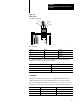
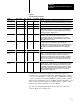
Connector and Pinout
The RS-232C interface connector at the Communications Controller end is
a DB-25 male connector with the following EIA (Electronics Industries
Association) pinout.
Connecting the
Communications Controller to
the RS232C Host