
Manual

Installing the Smart Transmitter Interface
Products
Chapter 2
2-8
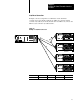
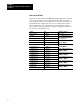
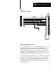
Connector and Pinout
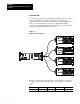
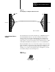
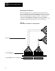
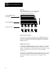
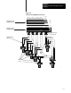
Attach the 17 position Phoenix COMBICON plugs (supplied) to each end
of the cable (see Figure 2.6) then plug them into the units. Use the bare
wire for chassis ground (to be connected at one end only, preferably to the
Communications Controller end). Use only one twisted pair for each "
pair of signals. The colors in the table below are intended as examples
only. You can use any pair you like for any pair of signals. The pinout for
the connector is in the table below.
Signal Pin Examples of Colors
Chassis Ground 1 (Shield) Bare Silver
+24 VDC 2 (Power) Red and White twisted pair;
RedisVDCWhiteisGround
Signal Ground 3 (Control)
Red is VDC, White is Ground
(see Appendix C)
+ Transmit Enable 4 (Control) Red and Black twisted pair;
Redis+Blackis
- Transmit Enable 5 (Control)
Red is +, Black is -
+ Channel Select 1 6 (Control) Blue and Black twisted pair
Blueis+Blackis
- Channel Select 1 7 (Control)
Blue is +, Black is -
+ Channel Select 2 8 (Control) White and Black twisted pair;
Whiteis+Blackis
- Channel Select 2 9 (Control)
White is +, Black is -
+ Channel Select 3 10 (Control) Orange and Black twisted pair;
Orangeis+Blackis
- Channel Select 3 11 (Control)
Orange is +, Black is -
+ Channel Select 4 12 (Control) Brown and Black twisted pair;
Brownis+Blackis
- Channel Select 4 13 (Control)
Brown is +, Black is -
+ Channel Select 5 14 (Control) Green and Black twisted pair;
Greenis+Blackis
- Channel Select 5 15 (Control)
Green is +, Black is -
+ HART Tx/Rx 16 (Control) Yellow and Black twisted pair;
Yellowis+Blackis
- HART Tx/Rx 17 (Control)
Yellow is +, Black is -