
Manual

Index
I–2
Digital signal, 18
Displays, 31
Duplicate message, 39
E
Electrical specifications
Communications Controller, A2
Terminal Block HT16, A4
Terminal Block HT8, A3
End of Message to RTS Off, 39
Environmental specifications
Communications Controller, A2
Terminal Block HT16, A4
Terminal Block HT8, A3
Error detection, 37
Exit, 32
without saving, 35
F
Factory defaults, 33
Fault, 53
hardware fault number, 35
indicator, 35
Faults, hardware, 53
Flow Control, 39
Format
diagnostic commands
Counter Reset, B3
Loop, B1
Read, B2
Status, B3
diagnostic replies
Counter Reset, B3
Loop, B1
Read, B2
Status, B3
Full duplex, 435
communications, 16
G
Grounding, 218
H
Half duplex, 435
communications, 17
Handshake, enabled/disabled, 39
Handshake signals, connection to IBM
computer with, 228
Hardware faults, 35, 53
HART
address, 45, 410
Command, 48, 411
delimiter, 45, 49
packet, 41, 44
burst data, 49
poll, 45
response, 49
protocol, 44
HART communications protocol, 18
and the Smart Transmitter Interface, 19
burst mode, 110
poll/response mode, 110
specifications, A5
I
Installation procedure
connecting the Controller to the Terminal
Blocks, 24
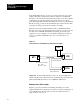
linear connection, 25
maximum cable lengths, C3
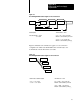
star connection, 26
grounding, 218
I/O connection
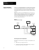
to 1771 I/O devices, 212
to HART field devices, 213, 214
mounting on DIN rail, 23
overview, 22
power supply connections
to the Communications Controller,
220
to the Terminal Blocks, C4
separate power supply to the Terminal
Blocks, C4
J
Jumper blocks, 220
Jumper positions for DSR and CTS lines
25 pin, 227
9 pin, 227
L
LEDs, interpreting
Communications Controller, 52