
Manual

Troubleshooting
Chapter 5
5-2
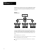
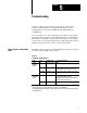
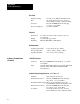
There are five status LEDs on the front panel of the Communications
Controller. These indicators can help you diagnose problems with the
module’s installation and operation.
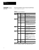
Table 5.B
Communications
Controller LED Indicators
LED: State Probable Cause Recommended Action
POWER
(green)
ON Normal operation None
OFF No power Replace fuse if blown
Ensure wiring to power connector is correct
FLASHING Intermittent contact Inspect power connector wiring for loose wire
RIO
(green)
ON Normal operation None
OFF Remote I/O fault Ensure wiring to remote connector is correct
Verify RIO communication parameter settings
(See Chapter 3)
FLASHING Not transmitting
data
Verify RIO communication parameter settings
Ensure only the last logical module in the rack
has its Last Module parameter set to Yes
Ensure that programmable controller is in RUN
mode
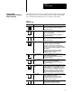
RS232
(green)
FLASHING Normal operation None (once you initiate active communications
on the RS232C link, this LED flashes to reflect
communication activity)
OFF No communication Check the RS232C parameters (Table 3.B,
parameters 48; Table 3.C, and the cable
connections and pinouts
HART
(green)
FLASHING Normal operation None (the Communications Controller is
receiving information from the HART field
devices)
OFF No communication Replace HART field device if faulty
Verify wiring from Communication Controller to
Terminal Blocks and from Terminal Blocks to
HART field device
Ensure power is being supplied to the HART
field device
Ensure LOOP POWER jumper on the Terminal
Block (Jpn) is correctly set
Ensure Terminal Block Board Address jumpers
are correctly set
FAULT
(red)
ON A fault has been
detected
See Table 5.C
OFF Normal operation None
Important: The RS-232 and HART LED indicators always stay off if
there is no communication activity on the communication channel.
Interpreting the
Communications Controller
Status LEDs