
Instruction Manual

DH II Overview
Chapter 4
4-3
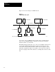
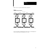
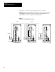
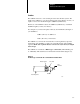
Figure 4.2 shows a typical redundant cabling configuration.
Figure 4.2
A
redundant cabling configuration.
Redundant
Node
Interface
Dropline
Dropline
Redundant
Node
Interface
Dropline
Dropline
Redundant
Node
Interface
Dropline
Dropline
Trunkline
Trunkline Trunkline Trunkline
Trunkline Trunkline Trunkline
Trunkline
Cable System A
Cable System B
16046
Tap Tap Tap
TapTapTap
For more information on DH II interface modules, refer to the Data Highway II
Local Area Network Overview (publication 1779-2.10).