
Owner manual


Rockwell Automation Publication 1769-IN088A-EN-P - February 2011 59
I/O Memory Mapping Chapter 3
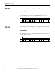
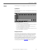
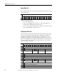
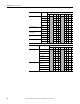
The bits are defined as follows:
• EC = Enable Channel.
• Inpt Dta Fm Chlx = Input Data Format Select.
• EA = Enable Alarm.
• AL = Alarm Latch.
• EI = Enable Interrupt.
(1)
• Inpt Tp/Rnge Sel Chlx = Input Type/Range Select.
• Inpt Filter Sel Chlx = Input Filter Select.
• Reserved = Allows for future expansion.
• ETS = Enable Time Stamp.
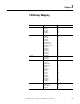
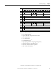
13 Reserved
14 EC Reserved EA AL EI Reserved Input Filter Sel Chl2
15 Reserved Inpt Dta Fm
Chl2
Reserved Inpt Tp/RngeSel
Chl2
16 S Process Alarm High Data Value Channel 2
17 S Process Alarm Low Data Value Channel 2
18 S Alarm Dead Band Value Channel 2
19 Reserved
20 EC Reserved EA AL EI Reserved Input Filter Sel Chl3
21 Reserved Inpt Dta Fm
Chl3
Reserved Inpt Tp/RngeSel
Chl3
22 S Process Alarm High Data Value Channel 3
23 S Process Alarm Low Data Value Channel 3
24 S Alarm Dead Band Value Channel 3
25 Reserved
(1) MicroLogix 1500 and CompactLogix L3x controllers do not support interrupts.
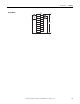
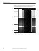
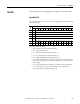
Word
Bit Position
1514131211109876543210