
User Manual

ControlLogix w/1769-ADN DeviceNet Ladder Example Program 7-15
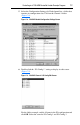
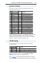
The PowerFlex 70 drives used in the example program have the
following parameter settings:
Note that the Data Out settings are set to match the respective Data In
settings for demonstration purposes only. This allows read/write
capability for the eight parameters selected and provides the ability to
verify that a change was made to a parameter value.
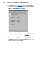
The 1769-SM1 used in the example program has the following
parameter settings:
Note that the module must be reset using Parameter 02 - [Reset
Module] before these parameter settings take effect.
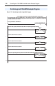
Refer to Chapter 4
for information about the I/O Image layout, Channel
Enable/Status, Logic Command/Status, Reference/Feedback, and Datalinks.
PowerFlex 70 Settings
Parameter
Setting Description
No. Name
90 Speed Ref A Sel 19 “DPI Port 2”
300 Data In A1 140 Parameter 140 - [Accel Time 1]
301 Data In A2 142 Parameter 142 - [Decel Time 1]
302 Data In B1 100 Parameter 100 - [Jog Speed]
303 Data In B2 155 Parameter 155 - [Stop Mode A]
304 Data In C1 101 Parameter 101 - [Preset Speed 1]
305 Data In C2 102 Parameter 102 - [Preset Speed 2]
306 Data In D1 103 Parameter 103 - [Preset Speed 3]
307 Data In D2 104 Parameter 104 - [Preset Speed 4]
310 Data Out A1 140 Parameter 140 - [Accel Time 1]
311 Data Out A2 142 Parameter 142 - [Decel Time 1]
312 Data Out B1 100 Parameter 100 - [Jog Speed]
313 Data Out B2 155 Parameter 155 - [Stop Mode A]
314 Data Out C1 101 Parameter 101 - [Preset Speed 1]
315 Data Out C2 102 Parameter 102 - [Preset Speed 2]
316 Data Out D1 103 Parameter 103 - [Preset Speed 3]
317 Data Out D2 104 Parameter 104 - [Preset Speed 4]
1769-SM1 Settings
Parameter
Setting Description
No. Name
07 I/O Config 1 11111 CH1 Command/Status and all Datalinks are enabled
24 I/O Config 2 11111 CH2 Command/Status and all Datalinks are enabled
41 I/O Config 3 11111 CH3 Command/Status and all Datalinks are enabled