
User Manual

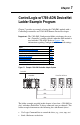

7-6 ControlLogix w/1769-ADN DeviceNet Ladder Example Program
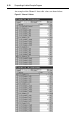
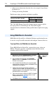
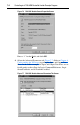
Figure 7.6 1769-SM1 Module General Properties Screen
Enter a “1” for the Bank, and click OK.
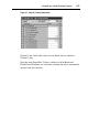
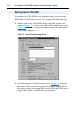
4. Select the Advanced Parameters tab (Figure 7.7
). Refer to Chapter 4,
Understanding the I/O Image regarding the Input and Output Data
Sizes. In the ladder example, the Input and Output Data Sizes are set
for 60 words each to allow for Logic Command/Reference, Logic
Status/Feedback, and all Datalinks enabled.
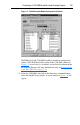
Figure 7.7 1769-SM1 Module Advanced Parameters Tab Screen