
User Manual

MicroLogix 1500 Ladder Example Program 5-3
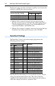
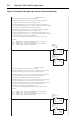
The 1769-SM1 used in the example program has the following
parameter settings:
Note that the module must be reset using Parameter 02 - [Reset
Module] before these parameter settings take effect.
Refer to Chapter 4 for information about the I/O Image layout, Channel
Enable/Status, Logic Command/Status, Reference/Feedback, and
Datalinks.
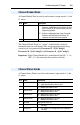
1769-SM1 Settings
Parameter
Setting Description
No. Name
07 I/O Config 1 11111 CH1 Command/Status and all Datalinks are enabled
24 I/O Config 2 11111 CH2 Command/Status and all Datalinks are enabled
41 I/O Config 3 11111 CH3 Command/Status and all Datalinks are enabled
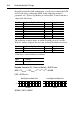
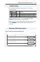
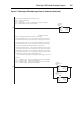
MicroLogix 1500 Example Program
Figure 5.2 MicroLogix 1500 Ladder Logic Main Program
MicroLogix 1500 w/ 1769-SM1 DPI/SCANport module example program
Execute the 1769-SM1 Channel 1 subroutine.
0000
JSR
Jump To Subroutine
SBR File Number U:3
JSR
Execute the 1769-SM1 Channel 2 subroutine.
0001
JSR
Jump To Subroutine
SBR File Number U:4
JSR
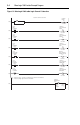
Execute the 1769-SM1 Channel 3 subroutine.
0002
JSR
Jump To Subroutine
SBR File Number U:5
JSR
0003
END