
User Manual

Chapter 5
MicroLogix 1500 Ladder Example
Program
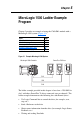
Chapter 5 provides an example of using the 1769-SM1 module with a
MicroLogix 1500 system (Figure 5.1).
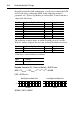
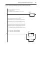
Figure 5.1 Example MicroLogix 1500 System
The ladder example provided in this chapter is based on a 1769-SM1 in
slot 1 with three PowerFlex 70 drives connected (one per channel). The
ladder example demonstrates the following for each channel (drive):
• Use Logic Command bits to control the drive (for example, start,
stop, etc.)
• Send a Reference to the drive
• Obtain status information from the drive (for example, Logic Status,
Feedback, etc.)
• Writing and reading Datalinks
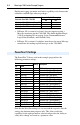
Topic Page
PowerFlex 70 Settings
5-2
1769-SM1 Settings 5-3
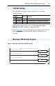
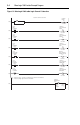
MicroLogix 1500 Example Program 5-3
Example Program Data Table 5-8
Using Explicit Messaging 5-10
PowerFlex 70 Drives
CH1
CH2
CH3
MicroLogix 1500 Controller