
User Manual

4-4 Understanding the I/O Image
The data valid bits (0-4) can be used in the user ladder program to
determine if the received data is valid and can be used. Bits 8-14 provide
general information about the connected product. Bits 6 and 7 provide
diagnostic feedback on the status of the 1769-SM1 module configuration.
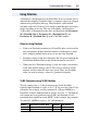
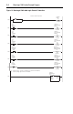
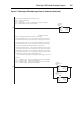
The Logic Command is a 16-bit word of control produced by the
controller and consumed by the 1769-SM1 module. The Logic Status is a
16-bit word of status produced by the 1769-SM1 module and consumed
by the controller.
This manual contains the bit definitions for compatible products
available at the time of publication in Appendix
E. For other products,
refer to their documentation.
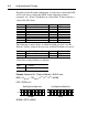
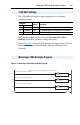
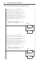
The Reference (16 bits or 32 bits) is produced by the controller and
consumed by the 1769-SM1 module. The Feedback (16 bits or 32 bits) is
produced by the 1769-SM1 module and consumed by the controller. The
size of the Reference/Feedback is determined by the drive and displayed
with Parameter 5 - [Ref/Fbk Size 1], Parameter 22 - [Ref/Fbk 2], and
Parameter 39 - [Ref/Fbk 3] in the 1769-SM1 module. For example, the
Reference/Feedback for CH1 is shown below:
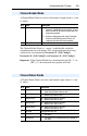
8-10 DPI/SCANport Port ID Bits 8, 9, & 10 represent the connected port # on the drive:
10
9 8
001 = Port 1
0 1 0 = Port 2 (typical)
011 = Port 3
100 = Port 4
101 = Port 5
110 = Port 6
111 = Port 7
11 SCANport Host “1” = a SCANport Host (1305, 1336 PLUS II, etc.) is
connected
12 DPI Host “1” = a DPI Host (PowerFlex 70, 700, etc.) is connected
13 32-bit Datalinks “0” = 16-bit Datalinks are used
“1” = 32-bit Datalinks are used
14 32-bit Ref/Fdbk “0” = 16-bit Reference / Feedback are used
“1” = 32-bit Reference / Feedback are used
15 Not used Reserved for future use
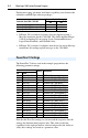
Using Logic Command/Status
Using Reference/Feedback
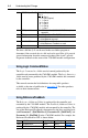
Size Valid Values Output Image Input Image Example
16-bit -32768 to 32767 Word 2 Word 2 Table 4.B
32-bit -2147483648 to 2147483647 Word 2 to 3 Word 2 to 3 Table 4.B