
User Manual

Understanding the I/O Image 4-3
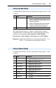
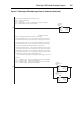
A Channel Enable Word is used for each channel (output words 0, 4, and
8), where:
The Channel Enable Word is a “master” enable/disable switch for
communications on each channel. The actual output/input data being
sent/received is determined by Parameter 07 - [I/O Config 1],
Parameter 24 - [I/O Config 2] and Parameter 41 - [I/O Config 3].
Important: If the Channel Enable bit is transitioned from ON (“1”) to
OFF (“0”), the connected drive product will fault.
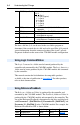
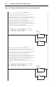
A Channel Status Word is used for each channel (input words 0, 4, and
8), where:
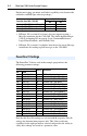
Channel Enable Words
Bit # Name Description
0 Channel Enable “0” = Disables sending output data (Logic Command/
Reference and Datalinks) to the channel. All input
data is zeroed (“0”) to indicate that the data is no
longer being updated.
“1” = Enables sending output data (Logic Command/
Reference and Datalinks) to the channel. All
respective input data will also be updated.
1-15 Not used Reserved for future use
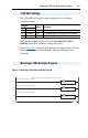
Channel Status Words
Bit # Name Description
0 Logic Status Valid “0” = Logic Status/Feedback data is not valid
“1” = Logic Status/Feedback data is valid
1 Datalink Out A “0” = Datalink Out A data is not valid
“1” = Datalink Out A data is valid
2 Datalink Out B “0” = Datalink Out B data is not valid
“1” = Datalink Out B data is valid
3 Datalink Out C “0” = Datalink Out C data is not valid
“1” = Datalink Out C data is valid
4 Datalink Out D “0” = Datalink Out D data is not valid
“1” = Datalink Out D data is valid
5 Not used Reserved for future use
6 Config Valid “1” = The module has a valid configuration (reported on
CH1 only)
7 Config Error “1” = The module has a configuration error (reported on
CH1 only)