
User Manual

Configuring the Module 3-11
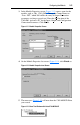
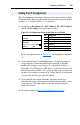
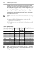
3. In the Module Properties screen (Figure 3.11), enter a name for the
module, such as “My_1769_SM1.” Change the Comm F
ormat to
“Data - INT,” which will enable the entry of Output Connection
parameters (no longer grayed out). Enter the Slot location of the
1769-SM1 and enter “60” for the I
nput, Output, and Configuration
Connection Parameters. Click Next >.
Figure 3.11 Module Properties Screen
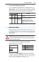
4. On the Module Properties last screen (Figure 3.12), click Finish >>.
Figure 3.12 Module Properties Last Screen
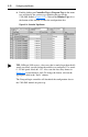
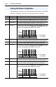
5. The menu tree (Figure 3.13) will now show the 1769-MODULE that
you created.
Figure 3.13 Menu Tree Window with Listed 1769-MODULE