
User Manual

Configuring the Module 3-3
* Note: Data for 16-bit Reference or 16-bit Datalinks are entered in these locations.
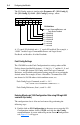
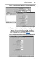
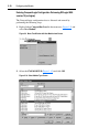
Idle Action / I/O Config Setting
The format for the Idle Action / I/O Config word is:
The Idle Action setting is similar to the Parameter 09 - [Idle Action 1], 26 -
[Idle Action 2] and 43 - [Idle Action 3] settings, where:
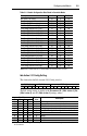
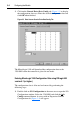
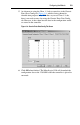
Table 3.A Module Configuration Data Words in Controller Mode
Description CH1 Word CH2 Word CH3 Word
Idle Action / I/O Config
0 4 8
Fault Config. Logic Command
1 5 9
Fault Config. Reference (Low) *
2 6 10
Fault Config. Reference (High)
3 7 11
Fault Config Datalink In A1 (Low) * 12 16 20
Fault Config Datalink In A1 (High) 13 17 21
Fault Config Datalink In A2 (Low) * 14 18 22
Fault Config Datalink In A2 (High) 15 19 23
Fault Config Datalink In B1 (Low) *
24 28 32
Fault Config Datalink In B1 (High)
25 29 33
Fault Config Datalink In B2 (Low) *
26 30 34
Fault Config Datalink In B2 (High)
27 31 35
Fault Config Datalink In C1 (Low) * 36 40 44
Fault Config Datalink In C1 (High) 37 41 45
Fault Config Datalink In C2 (Low) * 38 42 46
Fault Config Datalink In C2 (High) 39 43 47
Fault Config Datalink In D1 (Low) *
48 52 56
Fault Config Datalink In D1 (High)
49 53 57
Fault Config Datalink In D2 (Low) *
50 54 58
Fault Config Datalink In D2 (High)
51 55 59
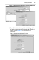
Not Used Idle Action I/O Config
15 14 13 1211109876543210
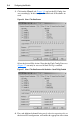
Idle Action Decimal
Value
Description
11 10 9 8
0 0 0 0 0 Fault - the connected drive is faulted
0 0 0 1 1 Stop - a Stop command is sent to the drive
(1)
0 0 1 0 2 Zero Data - zero's are sent to the drive
0 0 1 1 3 Hold Last - previous data continues to be sent to the drive
0 1 0 0 4 Send Fault Config - fault config data is sent to the drive
0 1 0 1 5 Invalid
0 1 1 0 6 Invalid
0 1 1 1 7 Invalid
0 0 0 0 8 Invalid
(1)
“Stop” Idle Action is not supported for SCANport connected channels. If this setting is used, the “Fault” action will
be used instead.