
Installation Instructions Owner's manual

Compact I/O DeviceNet Scanner Module 9
Publication 1769-IN060C-EN-P - May 2002
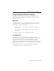
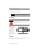
System Assembly
The module can be attached to an adjacent controller, power supply, or I/O
module. For mounting instructions, see “Panel Mounting” on page 10, or “DIN Rail
Mounting” on page 12. To work with a system that is already mounted, see
“Replacing a Single Module within a System” on page 13.
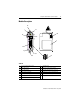
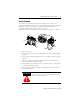
The following procedure shows you how to assemble the Compact I/O system.
1. Disconnect power.
2. Check that the bus lever of the module (A) is in the unlocked (fully right)
position.
3. Use the upper and lower tongue-and-groove slots (B) to secure the modules
together.
4. Move the module back along the tongue-and-groove slots until the bus
connectors (C) line up with each other.
5. Use your fingers or a small screw driver to push the bus lever back slightly
to clear the positioning tab (D).
6. Move the module’s bus lever fully to the left (E) until it clicks. Ensure it is
locked firmly in place.
ATTENTION
!
When attaching I/O modules, it is very important that the
bus connectors are securely locked together to ensure
proper electrical connection.
G
F
E
D
B
A
B
C