
Installation Instructions Owner's manual

Compact I/O DeviceNet Scanner Module 17
Publication 1769-IN060C-EN-P - May 2002
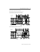
Data Organization
The scanner uses the input and output data images to transfer data, status and
command information between the scanner and the controller. The basic structure
is shown below. Refer to the
Compact I/O DeviceNet Scanner Module
User Manual,
publication 1769-UM009A-EN-P, for more detailed information.
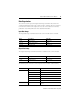
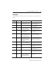
Input Data Image
The input data image is transferred from the scanner module to the controller.
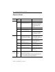
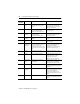
Output Data Image
The output data image is transferred from the controller to the scanner module.
The following table shows the bit descriptions for the Module Command Array.
Word Description Data Type
0 to 63 Status Structure 64-word array
64 and 65 Module Status Register 2 words
66 to 245 Input Data Image 180-word array
Word Description Data Type
0 and 1 Module Command Array 2-word array
2 to 181 Output Data Image 180-word array
Word Bit Operating Mode
0 0 1 = Run, 0 = Idle
1 1 = Fault
2 1 = Disable Network
3
Reserved
(1)
(1)
DO NOT manipulate Reserved Bits. Doing so may interfere with future compatibility.
4 1 = Reset
5 to 15
Reserved
(1)
10 to 15
Reserved
(1)