Installation Instructions Compact I/O DeviceNet Scanner Module (Cat. No. 1769-SDN) Inside... For More Information.............................................................................. 2 European Communities (EC) Directive Compliance ................................ 3 Hazardous Location Considerations ....................................................... 4 Environnements dangereux .................................................................... 4 Module Description ..........................
Compact I/O DeviceNet Scanner Module For More Information For Refer to this Document Pub. No. A more detailed description of how to use your DeviceNet Scanner Module Compact I/O DeviceNet Scanner Module User Manual 1769-UM009A-EN-P Detailed information on planning, mounting, wiring, and troubleshooting your CompactLogix System. CompactLogix System User Manual 1769-UM007C-EN-P Detailed information on planning, mounting, wiring, and troubleshooting your MicroLogix 1500 System.
Compact I/O DeviceNet Scanner Module 3 European Communities (EC) Directive Compliance This product carries the CE mark and is approved for installation within the European Union and EEA regions. It has been designed and tested to meet the following directives.
Compact I/O DeviceNet Scanner Module Hazardous Location Considerations This equipment is suitable for use in Class I, Division 2, Groups A, B, C, D or non-hazardous locations only. The following WARNING statement applies to use in hazardous locations. WARNING ! EXPLOSION HAZARD • Substitution of components may impair suitability for Class I, Division 2. • Do not replace components or disconnect equipment unless power has been switched off or the area is known to be non-hazardous.
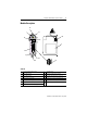
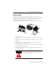
Compact I/O DeviceNet Scanner Module 5 Module Description 2A 1 3A 8B 8A 4 8B 5 9 7A 6 3B 2B 7B Table A 1 bus lever (with locking function) 6 grounding screw 2A upper DIN rail latch 7A DeviceNet mating male receptacle 2B lower DIN rail latch 7B removable DeviceNet female connector 3A upper panel mounting tab 8A movable bus connector with female pins 3B lower panel mounting tab 8B bus connector with male pins 4 Module and Network status LEDs 9 nameplate label 5 Address and E
Compact I/O DeviceNet Scanner Module Module Installation The 1769-SDN module is suitable for use in an industrial environment when installed in accordance with these instructions. Specifically, this equipment is intended for use in clean, dry environments (Pollution Degree 2(1)) and with circuits not exceeding Over Voltage Category II(2) (IEC 60664-1).
Compact I/O DeviceNet Scanner Module 7 Remove Power ATTENTION ! Remove power before removing or inserting this module. When you remove or insert a module with power applied, an electrical arc may occur.
Compact I/O DeviceNet Scanner Module System Planning Consider the following when planning your system: • The scanner can communicate with up to 63 DeviceNet devices. • The scanner, as a master, can own up to 63 slave I/O nodes. • The scanner can simultaneously be a master and be a slave owned by another DeviceNet master. • A 1769-ECR (right end cap) or 1769-ECL (left end cap) is required to terminate the end of the Compact I/O bus.
Compact I/O DeviceNet Scanner Module 9 System Assembly The module can be attached to an adjacent controller, power supply, or I/O module. For mounting instructions, see “Panel Mounting” on page 10, or “DIN Rail Mounting” on page 12. To work with a system that is already mounted, see “Replacing a Single Module within a System” on page 13. The following procedure shows you how to assemble the Compact I/O system. A D E C B G B F 1. Disconnect power. 2.
Compact I/O DeviceNet Scanner Module 7. Attach an end cap terminator (F) to the last module in the system by using the tongue-and-groove slots as before. 8. Lock the end cap bus terminator (G). A 1769-ECR or 1769-ECL right or left end cap must be used to IMPORTANT terminate the end of the serial communication bus. System Mounting ATTENTION ! During panel or DIN rail mounting of all devices, be sure that all debris (metal chips, wire strands, etc.) is kept from falling into the module.
Compact I/O DeviceNet Scanner Module 11 Panel Mounting Using the Dimensional Drawing NOTE: All dimensions are in mm (inches). Hole spacing tolerance: ±0.04 mm (0.016 in.). Compact I/O with CompactLogix Controller and Power Supply 50 mm (1.97 in) 35 mm (1.38 in) 70 mm (2.76 in) 35 mm (1.38 in) 35 mm 35 mm (1.38 in) (1.38 in) 28.5 mm (1.12 in) 147.4 mm (5.81 in) 35 mm (1.38 in) 35 mm (1.38 in) 118 mm (4.65 in) 59 mm (2.32 in) 40 mm (1.58 in) 59 mm (2.32 in) 122.6 mm (4.83 in) 132 mm (5.
Compact I/O DeviceNet Scanner Module Panel Mounting Procedure Using Modules as a Template The following procedure allows you to use the assembled modules as a template for drilling holes in the panel. Due to module mounting hole tolerance, it is important to follow these procedures: 1. On a clean work surface, assemble no more than three modules. 2. Using the assembled modules as a template, carefully mark the center of all module-mounting holes on the panel. 3.
Compact I/O DeviceNet Scanner Module 13 Replacing the Scanner Module within a System The scanner can be replaced while the system is mounted to a panel (or DIN rail). 1. Remove power. See important note on page 7. 2. Remove the DeviceNet cable from the scanner by removing the DeviceNet connector. 3. Remove the upper and lower mounting screws from the scanner (or open the DIN latches using a flat-blade screwdriver). 4.
Compact I/O DeviceNet Scanner Module 11. Restore scanner configuration using RSNetWorx for DeviceNet. IMPORTANT Be sure that the new module has the same node address and baud rate as the module that was replaced. Field Wiring Connections Grounding the Scanner Module This product is intended to be mounted to a well-grounded mounting surface such as a metal panel.
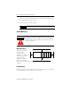
Compact I/O DeviceNet Scanner Module 15 DeviceNet Wiring DeviceNet Connector Grounding Screw Use #14 AWG wire to connect to panel ground. Connect(1) To Red Wire V+ White Wire CAN High Bare Wire Shield Blue Wire CAN Low Black Wire V- 1. Connect the DeviceNet cable to the removable connector as shown. 2. Insert the removable female connector into the mating male connector on the DeviceNet scanner module. 3.
Compact I/O DeviceNet Scanner Module Configuring the 1769-SDN on DeviceNet The 1769-SDN must be configured using a DeviceNet configuration tool. The recommended configuration software is RSNetWorx for DeviceNet (version 3.00 or higher). TIP If your RSNetWorx configuration software does not include the required EDS (Electronic Data Sheet) file, it is available via http://www.ab.com/networks/eds.
Compact I/O DeviceNet Scanner Module 17 Data Organization The scanner uses the input and output data images to transfer data, status and command information between the scanner and the controller. The basic structure is shown below. Refer to the Compact I/O DeviceNet Scanner Module User Manual, publication 1769-UM009A-EN-P, for more detailed information. Input Data Image The input data image is transferred from the scanner module to the controller.
Compact I/O DeviceNet Scanner Module Diagnostic Indicators Indicator Color/ Status Indicates Recommended Action Module Off No power applied to module. Apply power. Flashing Green No Bus Master (MicroLogix or CompactLogix controller) present. Verify module connectors are properly seated. If they are, cycle power to the controller. If this does not correct the problem, replace the controller. If replacing the controller does not correct the problem, replace the 1769-SDN.
Compact I/O DeviceNet Scanner Module 19 Error Codes The following table describes the Error Codes indicated by the 7-segment numeric display. Code (decimal) Name Description Recommended Action 70 Duplicate Node Controller has Failed Duplicate Node Address Check. The node address selected is already in use. Change the module’s or conflicting device’s network address (node number) to an available one. 71 Illegal Scan List Data Illegal data in Scan List.
Compact I/O DeviceNet Scanner Module Code (decimal) Name Description Recommended Action 82 Fragmentation Error Error detected in sequence of fragmented I/O messages from device. Check scan list table entry for slave device to make sure that input and output data lengths are correct. Check slave device configuration. 83 Slave Init Error Slave device is returning error responses when the module attempts to communicate with it. Check slave device’s configuration. Reboot slave device.
Compact I/O DeviceNet Scanner Module 21 Specifications General Specifications Specification Value Module Dimensions 118 mm (height) x 87 mm (depth) x 35 mm (width) height including mounting tabs is 138 mm 4.65 in. (height) x 3.43 in (depth) x 1.38 in (width) height including mounting tabs is 5.43 in. Approximate Shipping Weight (with carton) 280g (0.61 lbs.
Compact I/O DeviceNet Scanner Module Electrical and DeviceNet Specifications Specification Value Bus Current Draw (maximum) 440 mA at 5V dc (2.2 Watts) DeviceNet Power Requirements N.E.C. Class 2 90 mA at 11V dc (maximum) 110 mA at 25V dc (maximum) 200 mA for 1.5 ms (inrush) Heat Dissipation (maximum) 3.
Compact I/O DeviceNet Scanner Module 23 Notes: Publication 1769-IN060C-EN-P - May 2002
Publication 1769-IN060C-EN-P - May 2002 Supersedes Publication 1769-IN060B-EN-P - September 2001 PN 40072-107-01(3) Copyright © 2002 Rockwell Automation. All rights reserved. Printed in the U.S.A.