
User manual


82 Rockwell Automation Publication 1769-UM011I-EN-P - February 2013
Chapter 6 Place, Configure, and Monitor I/O
Validate I/O Layout
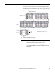
After you have selected your I/O modules, you need to validate the system you
want to design. Before you begin to place your I/O modules, consider that the
minimum backplane RPI increases as you add modules. Also, the I/O modules
must be distributed so that the current consumed from the left or right side of the
power supply never exceeds 2.0 A at 5V DC or 1.0 A at 24V DC.
Estimate Requested Packet Interval
The requested packet interval (RPI) defines the frequency at which the
controller sends and receives all I/O data on the backplane. Each module on the
backplane can have its own individual RPI setting.
The effective scan frequency for any individual module is still impacted by the
other modules in the system and those modules’ RPI settings. The following table
provides relative scanning durations for various types of modules. This
information should be taken into account when setting an individual module’s
RPI in order to achieve the desired effective scan frequency for any module in the
system.
You can always select an RPI that is slower than these. The RPI shows how
quickly modules can be scanned, not how quickly an application can use the data.
The RPI is asynchronous to the program scan. Other factors, such as program
execution duration, affect I/O throughput.
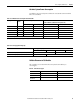
Type of Module Request Packet Interval
Digital and analog (any mix) • 1…4 modules can be scanned in 1 ms.
• 5…30 modules can be scanned in 2 ms.
• Some input modules have a fixed 8 ms filter, so selecting a greater RPI has
no effect.
Specialty • Full-sized 1769-SDN modules add 2 ms per module.
• 1769-HSC modules add 1 ms per module.
• Full-sized 1769-ASCII modules add 1 ms per module.