
Technical data


Rockwell Automation Publication 1769-TD006C-EN-P - March 2012 5
1769 Compact I/O Modules Specifications
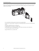
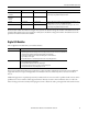
Each 1769 I/O module has a distance rating. In 1769 systems, the distance rating is the number of modules between the
specific module and the 1769 power supply. In a 1768 system, the distance rating is the number of modules between the
specific I/O module and the 1768 controller.
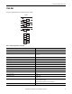
Digital I/O Modules
Choose digital I/O modules when you need these features.
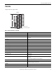
Most output modules have built-in surge suppression to reduce the effects of high-voltage transients. Use an additional
suppression device if an output is being used to control inductive devices, such as relays, motor starters, solenoids, or
motors.
Additional suppression is especially important if your inductive device is in series with or parallel to hard contacts, such as
pushbuttons or selector switches. Add a suppression device directly across the coil of an inductive device to reduce the
effects of voltage transients caused by interrupting the current to that device and to prolong the life of the switch contacts.
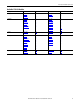
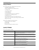
1769-L35CR
1769-L35E
30 local modules 3 separate banks The additional banks are powered by standard 1769 power supplies and connect to
the main rack by using standard 1769 expansion cables.
1769-L32C
1769-L32E
1769-L31
16 local modules 3 separate banks
1768-L43 16 local modules 3 separate banks As many as eight 1769 local modules can be attached to the 1768 backplane. The
remaining modules can be in one or two additional I/O banks.
The additional banks are powered by standard 1769 power supplies and connect to
the main rack by using standard 1769 expansion cables.
1768-L45 30 local modules 3 separate banks
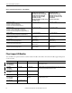
Type Description
Input An input module responds to an input signal in the following manner:
• Input filtering limits the effect of voltage transients caused by contact bounce and/or electrical noise. If not filtered,
voltage transients could produce false data. All input modules use input filtering.
• Optical isolation shields logic circuits from possible damage due to electrical transients.
• Logic circuits process the signal.
• An input indicator turns on or off indicating the status of the corresponding input device.
Output An output module controls the output signal in the following manner:
• Logic circuits determine the output status.
• An output indicator displays the status of the output signal.
• Optical isolation separates module logic and bus circuits from field power.
• The output driver turns the corresponding output on or off.
Controller Supports Location Considerations