
Specifications


118 Rockwell Automation Publication 1769-TD006E-EN-P - January 2015
1769 Compact I/O Modules Specifications
1769-HSC
Compact high-speed counter module
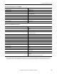
External resistors are required if they are not internal to the encoder. The pull-up resistor (R) value depends on the power
supply value. To calculate the maximum resistor value, the following formula:
where:
• R = maximum pull-up resistor value
• VDC = power supply voltage
• Vmin = 2.6V DC
• min = 6.8 mA
The minimum resistor (R) value depends on the current sinking capability of the encoder.
Power Supply Voltage (V DC) Pull-up Resistor Value Max (R)
(1)
(1) Resistance values may change, depending upon your application.
5V DC 352 Ω
12V DC 1382 Ω
24V DC 3147 Ω
A
A
B
B
Z
Z
A1(+)
A1(–)
B1(+)
B1(–)
Z1(+)
Z1(–)
GND
VS
+VDC
COM
Cable
Power
Supply
Allen-Bradley
845H Series
differential
encoder
Shield/Housing
Connect only if housing is electronically isolated
from the motor and ground.
Shield
Module Inputs
Earth
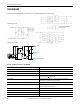
Differential Encoder Wiring
See the encoder manual for proper cable type. The type of
cable used should be twisted pair, individually shielded
cable with a maximum length of 300 m (1000 ft).
Single-ended Encoder Wiring
A
B
Z
A1(+)
A1(–)
B1(+)
B1(–)
Z1(+)
Z1(–)
GND
VS
+VDC
COM
R
(2)
Cable
Power
Supply
Allen-Bradley
845H Series
single-ended
encoder
Shield/Housing
Connect only if housing is electronically isolated
from the motor and ground.
Shield
Module Inputs
Earth
See the encoder manual for proper cable type. The type of
cable used should be twisted pair, individually shielded
cable with a maximum length of 300 m (1000 ft).
R
V
dcVmin–()
Imin
--------------------------------------=