
Specifications


12 Compact I/O Expansion Power Supplies
Publication 1769-IN028B-EN-P - October 2008
Additional cooling provisions might be necessary when high ambient temperatures are
encountered.
Mount the Panel
Mount the power supply to a panel by using four screws per module. Use M4 or #8 panhead
screws. Mounting screws are required on each power supply panel mounting tab.
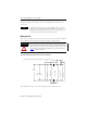
Panel Mounting Using the Dimensional Template
Note: All dimensions are in mm (in.). Hole spacing tolerance: ±0.4 mm (0.016 in.)
TIP
Do not bring in unfiltered outside air. Place the Compact I/O system in an enclosure to
protect it from a corrosive atmosphere. Harmful contaminants or dirt could cause
improper operation or damage to components. In extreme cases, you may need to use air
conditioning to protect against heat build-up within the enclosure.
ATTENTION
This product is intended to be mounted to a well-grounded mounting surface such as a
metal panel. Additional grounding connections from the power supply's mounting tabs or
DIN rail (if used) are not required unless the mounting surface cannot be grounded. Refer
to Industrial Automation Wiring and Grounding Guidelines, Allen-Bradley publication
1770-4.1
, for additional information.
Compact I/O
Compact I/O
End Cap
End Cap
Power Supply
For more than 2 modules: (number of modules -1) X 35 mm (1.38 in.)
132
(5.197)
40
(1.58)
70
(2.76)
28.5
(1.12)
35
35
122,6±0.2
(4.826±0.008)
(1.38)
(1.38)