
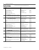
Specifications


6
1768-SG001A-EN-P -- March 2006
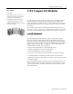
CompactLogix Selection Guide
When planning I/O communications, consider:
y which Compact I/O modules to use.
y where to place Compact I/O modules.
y how Compact I/O modules operate.
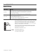
TTyyppee ooff MMoodduullee DDeessccrriippttiioonn
Input module
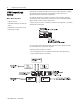
An input module responds to an input signal in the following manner:
• Input filtering limits the effect of voltage transients caused by contact bounce and/or electrical noise. If not
filtered, voltage transients could produce false data. All input modules use input filtering.
• Optical isolation shields logic circuits from possible damage due to electrical transients.
• Logic circuits process the signal.
• An input LED turns on or off indicating the status of the corresponding input device.
Output module
An output module controls the output signal in the following manner:
• Logic circuits determine the output status.
• An output LED indicates the status of the output signal.
• Optical isolation separates module logic and bus circuits from field power.
• The output driver turns the corresponding output on or off.
Most output modules have built-in surge suppression to reduce the effects of high-voltage
transients. Use an additional suppression device if an output is being used to control
inductive devices, such as relays, motor starters, solenoids, or motors. Additional
suppression is especially important if your inductive device is in series with or parallel to
hard contacts, such as push buttons or selector switches.
Add a suppression device directly across the coil of an inductive device to reduce the
effects of voltage transients caused by interrupting the current to that device and to
prolong the life of the switch contacts.
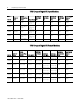
DDiiggiittaall II//OO MMoodduulleess