768 CompactLogix Selection Guide 1768-L43
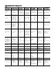
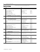
Logix Controllers Comparison Common Characteristics 1768 1756 ControlLogix CompactLogix Controller tasks: • Continuous • Periodic • Event • 32 tasks (only 1 continuous) • event tasks: supports all event triggers User memory 1756-L55M12: 750 KB 1756-L55M13: 1.5 MB 1756-L55M14: 3.5 MB 1756-L55M16: 7.5 MB 1756-L55M22: 750 KB 1756-L55M23: 1. 5 MB 1756-L55M24: 3.
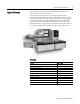
CompactLogix Selection Guide Logix Platforms 1 Allen-Bradley Logix platforms provide a single integrated control architecture for sequential, drives, motion, and process control. The Logix platforms provide a common control engine, programming software environment, and communication support across multiple hardware platforms. All Logix controllers operate with a multitasking, multiprocessing operating system and support the same set of instructions in multiple programming languages.
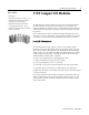
2 CompactLogix Selection Guide 1768 CompactLogix System CompactLogix is designed to provide a Logix solution for medium applications. Typically, these applications are machine-level control applications with motion axes, I/O requirements, and network connectivity requirements. What's New in Version 15: The 1768-L43 controller offers one built-in serial port. Install an optional 1768-ENBT communication module for EtherNet/IP communications.
CompactLogix Selection Guide 3 The 1768 CompactLogix controller combines both a 1768 backplane and a 1769 backplane. This provides the advantages of the 1768 architecture while retaining the advantages of 1769 I/O support.
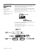
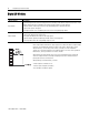
4 CompactLogix Selection Guide Specify a System 9 Step 1 Follow these steps as you specify your CompactLogix system: See Select I/O devices Use a system spreadsheet to record: • Location of the device • Number of points needed • Appropriate catalog number • Number of points available per module • Number of modules 2 Select motion control and drives requirements To the system spreadsheet, add the number of motion modules.
CompactLogix Selection Guide Step 1 - Select: y I/O modules 5 1769 Compact I/O Modules y 1492 wiring system (if you want to use a wiring system instead of the terminal block that comes with module) y PanelConnect modules and cables if connecting input modules to sensors y 1769-CRLx expansion cables for multiple banks of I/O modules The 1769 Compact I/O modules can be used as local I/O for a CompactLogix controller. Install the I/O modules on a panel with two mounting screws or on a DIN rail.
6 CompactLogix Selection Guide Digital I/O Modules Type of Module Input module Output module Description An input module responds to an input signal in the following manner: • Input filtering limits the effect of voltage transients caused by contact bounce and/or electrical noise. If not filtered, voltage transients could produce false data. All input modules use input filtering. • Optical isolation shields logic circuits from possible damage due to electrical transients.
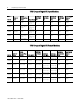
CompactLogix Selection Guide 7 1769 Compact Digital AC Input Modules Cat. No. Number of Inputs 1769-IA8I 8 individually isolated Input Delay Voltage Time, ON to Category/Type, Input Voltage Range OFF Current, OnState Input, Min. Current, OffState Input, Max. Backplane Current (mA) at 5V Power Supply Distance Rating 100 or 120V ac 79...132V ac @ 47...63Hz 20 ms 5 mA @ 79V ac 2.5 mA 90 mA 8 modules 1769-IA16 16 100 or 120V ac 79...132V ac @ 4763Hz 20 ms 5 mA @ 79V ac 2.
8 CompactLogix Selection Guide 1769 Compact Digital DC Input Modules Number of Inputs Cat. No. Input Delay Voltage Time, ON to Category/Type , Input Voltage Range OFF Current, OnState Input, Min. Current, OffState Input, Max. Backplane Current (mA) at 5V Power Supply Distance Rating 1769-IQ6XOW4 6 24V dc, sinking or sourcing 10...30V dc @ 30 °C (86 °F) 8 ms 10...26.4V dc @ 60 °C (140 °F) 2 mA 1.5 mA 105 mA 8 modules 1769-IQ16 16 24V DC, sinking or sourcing 10...
CompactLogix Selection Guide 9 1769 Compact Digital Contact Output Modules Cat. No. Number of Outputs Voltage Category/Ty Voltage pe, Output Range Leakage Current, OffCurrent per State Current per Module, Output, Max Output, Max. Max. Power Backplane Backplane Supply Current (mA) Current (mA) Distance at 5V Rating at 24V 1769-IQ6XOW4 4 24V dc 5...265V ac 5...125V dc 0 mA 2.5 A 8.0 A 105 mA 50 mA 8 modules 1769-OW8 8 24V dc 5...265V ac 5...125V dc 0 mA 0.5 A @ 60 °C (140 °F) 16 A 1.
10 CompactLogix Selection Guide 1769 Compact Analog Modules Cat. No. Number of Inputs Number of Outputs Resolution, Bits Signal Range Sensors Supported Backplane Current (mA) at 5V Backplane Current (mA) at 24V Power Supply Distance Rating — 105 mA 60 mA 8 modules 1769-IF4 4 — 14 bits (unipolar) 0…20 mA 4…20 mA 0…10V dc ±10V dc 0…5V dc 1…5V dc 1769-IF4I 4 individually isolated ⎯ 16 bits (unipolar) ±10.5V dc -0.5…10.5V dc -0.5...5.25V dc 0.5…5.
CompactLogix Selection Guide Specialty I/O Modules 11 Specialty I/O modules are available for more application-specific needs. 1769-HSC High-speed Counter Module Use the 1769-HSC when you need: y a counter module that is capable of reacting to high-speed input signals y to generate rate and time-between-pulses (pulse interval) data y as many as 2 channels of quadrature or 4 channels of pulse/count inputs Cat. No.
12 CompactLogix Selection Guide 1492 Wiring Systems As an alternative to buying RTBs and connecting the wires yourself, you can buy a wiring system of: y interface modules (IFMs) that provide the output terminal blocks for digital I/O modules. Use the pre-wired cables that match the I/O module to the IFM. y analog interface modules (AIFMs) that provide the output terminal blocks for analog I/O modules. Use the pre-wired cables that match the I/O module to the AIFM. y I/O-module-ready cables.
CompactLogix Selection Guide Place Compact I/O Modules in a CompactLogix System 13 You can DIN-rail or panel mount the controller and I/O modules. The number of local I/O modules supported depends on the controller. This Controller Supports That Can Be In 1768-L43 16 local modules 3 separate banks Each 1769 I/O module has a distance rating. In 1769 systems, the distance rating is the number of modules between the specific module and the 1769 power supply.
14 CompactLogix Selection Guide Select End Caps The final I/O bank in the CompactLogix system needs an end cap on the end without the expansion cable. For a Right end cap Left end cap Order 1769-ECR 1769-ECL Plan Local and Remote (Distributed) I/O In addition to local I/O, the CompactLogix controller can control remote (distributed) I/O via the: y EtherNet/IP network using a 1768-ENBT communication module. y DeviceNet network using a 1769-SDN scanner module.
CompactLogix Selection Guide Step 2 - Select: y Size the motion application (use the Motion Analyzer) y How you want to interface the controller and drives y A SERCOS interface module y Associated cables y Select drives, motors, and accessories (use the Motion Analyzer) 15 Motion Control Requirements The Logix approach to motion control employs synchronized, distributed processing and provides a highly-integrated motion solution.
16 CompactLogix Selection Guide Motion Performance The 1768 CompactLogix controller supports one 1768-M04SE SERCOS interface module for: y as many as four Kinetix drives and motors. y as many as two feedback axes. y as many as six virtual axes. In a motion application: y You can have as many as four axes per CompactLogix system. If your solution requires more than four Kinetix drives, consider the ControlLogix platform.
CompactLogix Selection Guide 17 Typical Configuration - 2-Axis Motion with Ultra3000 Servo Drives y If you have an auxiliary feedback device that requires encoder feedback, change the Ultra3000 drives to Kinetix 6000 drives. y If you tie an incremental encoder to a 1769-HSC High-speed Counter module, you cannot use this input as one of the feedback-only axes or tie this input to the motion planner.
18 CompactLogix Selection Guide Typical Configuration - 3-Axis Integrated Motion with Kinetix Servo Drives A 3-axis system with Kinetix drives supports: y execution of 4 axes per 1 ms. y velocity bandwidth > 400 Hz and current loop bandwidth > 1000 Hz. y high resolution, unlimited travel, and absolute feedback features. y two feedback ports per Kinetix drive.
CompactLogix Selection Guide 19 Typical Configuration - 4-Axis Integrated Motion with Kinetix drives and LIM power interface A 4-axis system with Kinetix drives supports: y execution of 4 axes per 1 ms. y velocity bandwidth > 400 Hz and current loop bandwidth > 1000 Hz. y high resolution, unlimited travel, and absolute feedback features. y two feedback ports per Kinetix drive. y optional 2094 Line Interface Module (LIM) as the incoming power source for an entire control panel.
20 CompactLogix Selection Guide Cables for Use with the SERCOS Interface Modules Both the transmitter and receiver connections use a F-SMA standard plug that conforms to the F-SMA screw type connector. Select one of these fiber optic cables to connect the SERCOS interface module to the drive. Cat. No. 2090-SCEPx-x (no jacket) 2090-SCVPx-x (standard jacket) 2090-SCNPx-x (nylon jacket) 2090-SCVGx-x Description Plastic Fiber Optic Cables 1000 μm plastic simplex fiber optic cable transmission range of 1.
CompactLogix Selection Guide Step 3 - Select: y Networks 21 Network Communications y Communication interfaces y Associated cables and network equipment You use separate interface modules to connect to different networks. y The 1768-L43 controller has a built-in serial port. y Add a 1768-ENBT module for EtherNet/IP communications. y Add a 1769-SDN scanner to connect to DeviceNet devices.
22 CompactLogix Selection Guide Select a Network If Your Application Requires • Plant management • Configuration, data collection, and control on a single, high-speed network • Time-critical applications with no established schedule • Data sent regularly • Internet/Intranet connection • Connections of low-level devices directly to plant floor controllers, without interfacing them through I/O modules • Data sent as needed • More diagnostics for improved data collection and fault detection • Less wiring an
CompactLogix Selection Guide EtherNet/IP Network 23 The Ethernet Industrial (EtherNet/IP) network protocol is an open industrial networking standard that supports both real-time I/O messaging and message exchange. It emerged due to the high demand for using the Ethernet network for control applications. The EtherNet/IP network uses off-the-shelf Ethernet communication chips and physical media.
24 CompactLogix Selection Guide EtherNet/IP Product Compatibility Recipient EtherNet/IP PLC-5 or SLC 5/05 1785-ENET Processor Module EtherNet/IP PLC-5 or SLC 5/05 Processor information 1785-ENET Module Logix5000 Controller 1794-AENT FLEX I/O Adapter 1734-AENT POINT I/O Adapter 1761-NETENI Interface PanelView Plus EtherNet/IP RSLinx Terminal Software 1761-NETENI Interface information information not supported not supported information information information information information infor
CompactLogix Selection Guide DeviceNet Network 25 The DeviceNet network is an open low-level network that provides connections between simple industrial devices (such as sensors and actuators) and higher-level devices (such as PLC controllers and computers). The DeviceNet network uses the proven Common Industrial Protocol (CIP) to provide the control, configure, and data collection capabilities for industrial devices.
26 CompactLogix Selection Guide DeviceNet Interface Specifications Cat. No. Communication Rate Cable 90 mA @ 11V dc 110 mA @ 25V dc (N.E.C. Class 2) 1769-SDN 1761-NET-DNI 1769-ADN/B DeviceNet Power Requirements, Max. 125 Kbps 250 Kbps 500 Kbps Power Consumption (W) at 24V Backplane Current (mA) at 5V Backplane Current (mA) at 24V Power Supply Distance Rating 2.
CompactLogix Selection Guide Serial Network Use This DF1 Mode Point to point DF1 master DF1 slave User mode (ASCII) 27 The serial port is compatible with RS-232 serial communication. The serial port supports the DF1 protocol to communicate with other devices on the serial link.
28 CompactLogix Selection Guide DH-485 Network On the DH-485 network, the controller can send and receive messages to and from other controllers on the network. The DH-485 connection does support remote programming and monitoring via RSLogix 5000 software. However, excessive traffic over a DH-485 connection can adversely affect overall performance and can lead to timeouts and loss in RSLogix 5000 configuration performance.
CompactLogix Selection Guide Step 4 - Select: y A controller with sufficient memory 29 1768 CompactLogix Controllers y A 1784-CF64 CompactFlash card y No batteries required The 1768 CompactLogix controller provides a scalable controller solution that supports SERCOS motion, the EtherNet/IP and DeviceNet networks, and can address a maximum of 16 local 1769 I/O modules. The 1768 CompactLogix controllers can monitor and control I/O across the 1769 CompactBus, as well as over distributed I/O links.
30 CompactLogix Selection Guide 1768 Controller Design The 1768 CompactLogix controller is the rightmost module in the 1768 backplane. In addition to the controller, you can have a maximum of two 1768 modules. These modules can be combination of: y two 1768 ENBT EtherNet/IP modules, or y one 1768 ENBT EtherNet/IP module and one 1768-M04SE SERCOS interface module. The 1768 system supports a maximum of only one 1768-M04SE SERCOS interface module.
CompactLogix Selection Guide 31 Controller Placement Follow these guidelines as you place modules in the 1768 backplane: y The 1768 power supply must be the leftmost module in the 1768 backplane. y The controller must be the rightmost module in the 1768 backplane. y As many as two additional 1768 modules can be between the controller and power supply.
32 CompactLogix Selection Guide 1768 Controller Compatibility Control Distributed I/O Modules The 1768 CompactLogix controller can control these distributed I/O modules.
CompactLogix Selection Guide 33 Communicate with Other Controllers The 1768 CompactLogix controller can communicate with these controllers.
34 CompactLogix Selection Guide How a Logix System Uses Tasks A Logix controller uses three types of tasks. Use the following table to choose the appropriate type of task for each section of your logic. To Execute a Section of Logic Use This Type of Task All of the time Continuous task • At a constant period (e.g.
CompactLogix Selection Guide How a Logix System Uses Connections 35 A Logix system uses a connection to establish a communication link between two devices.
36 CompactLogix Selection Guide Connections for Produced and Consumed Tags This Type of Tag Produced Consumed The controller supports the ability to produce (broadcast) and consume (receive) systemshared tags over EtherNet/IP networks. Produced and consumed tags each require connections. Requires These Connections A produced tag allows other controllers to consume the tag, which means that a controller can receive the tag data from another controller.
CompactLogix Selection Guide Connections Example 37 You do not need to consider any connections between the 1768 controller and its 1769-SDN scanners. The controller supports multiple 1769-SDN sacnners. In this example system the 1768-L43 controller: y sends and receives messages to/from the 1756 ControlLogix controller and the 1769-L35E CompactLogix controller over the EtherNet/IP network. y controls remote I/O devices on the EtherNet/IP network.
38 CompactLogix Selection Guide Determine Total Connection Use The total connection requirements for a 1768 CompactLogix system include both local and remote (distributed) connections. Tallying local controller connections is not an issue because the controllers supports all the connections required for the maximum number of I/O modules and 1769-SDN scanners in one system.
CompactLogix Selection Guide Step 5 - Select: y 1768 power supply 39 Power Supplies y For more than eight 1769 modules, additional 1769 power supplies as needed The 1768 backplane requires one 1768 power supply. The power supply is a dual input supply that operates in multiple ranges: • 86 to 265V ac • 108 to 132V dc The power supply also offers a 24V dc external power source. The CompactLogix power supply requires that a 1768 CompactLogix controller be installed to power the system.
40 CompactLogix Selection Guide Select 1768 Power Supplies Cat. No. 1768-PA3 Description 85…265 V ac 108…132 V dc Backplane Current Supports: • one 1768 controller (required) • as many as two additional 1768 modules Power Consumption, Max. 24V dc User Power Capacity Inrush Current, (0 ...60 C) Max. 120 VA/120 W, line harmonics Per EN61000-3-2 250 mA 20 A @ 125V ac 20 A @ 120V dc 37 A @ 240V ac Line Loss Ride Through 5 ms...10 s For: • total current 3.
CompactLogix Selection Guide Select 1769 I/O Power Supplies 41 Each additional bank of I/O modules requires a 1769 power supply. Place 1769 I/O modules to the left or the right of the 1769 power supply. As many as eight I/O modules can be placed on each side of the power supply. Each 1769 module also has a power supply distance rating (the number of modules from the power supply). Each module must be located within its distance rating.
42 CompactLogix Selection Guide 1769 Power Requirements and Transformer Sizing 1768-SG001A-EN-P -- March 2006
CompactLogix Selection Guide Step 6 - Select: y Panel mount or DIN rail mount 43 Mount the CompactLogix System y Appropriate number of panels or DIN rails based on the number of modules and the physical location y Expansion cables y One end cap per controller system You can panel mount or DIN-rail mount a CompactLogix system. The CompactLogix system must be mounted so that the modules are horizontal to each other. If you decide to use a DIN rail, use steel, 35 x 7.
44 CompactLogix Selection Guide Ground the System Ground a CompactLogix system through the: y non-coated, steel DIN rail. y panel-mount screw hole containing the ground strap.
CompactLogix Selection Guide Step 7 - Select: y RSLinx Enterprise software 45 Select ViewAnyWare Products y Operator interface terminal or computer ViewAnyWare products, together with Logix for control and NetLinx architecture for communication, make up Rockwell Automation’s Integrated Architecture strategy. The ViewAnyWare strategy combines Rockwell Automation’s expertise in Allen-Bradley electronic operator interface and industrialized PC hardware with Rockwell Software’s supervisory control software.
46 CompactLogix Selection Guide PanelView Plus Terminal The PanelView Plus terminal is ideal for applications with a need to monitor, control, and display information graphically, allowing operators to quickly understand the status of their application. PanelView Plus terminals come with RSView Studio software and have embedded RSView Machine Edition software functionality.
CompactLogix Selection Guide Step 8 - Select: y The appropriate package of RSLogix 5000 Enterprise Series software and any options y Other software packages for your application y An appropriate operator interface 47 Software and Operator Interface Your selection of modules and network configuration determines what software packages you need to configure and program your system.
48 CompactLogix Selection Guide Programming Software RSLogix 5000 Enterprise Series software is designed to work with Rockwell Automation’s Logix platforms. RSLogix 5000 Enterprise Series software is an IEC 61131-3 compliant software package that offers relay ladder, structured text, function block diagram, and sequential function chart editors for you to develop application programs. RSLogix 5000 Enterprise Series software also includes axis configuration and programming support for motion control.
ControlLogix Selection Guide 49 Select the RSLogix 5000 Enterprise Series Software Package Available Features Service Edition 9324- Mini Edition RLD000xxE 9324♠ RLD200xxE Logix5000 controllers supported all♠ Relay ladder diagram editor§ Lite Edition 9324RLD250xxE CompactLogix FlexLogix CompactLogix FlexLogix view only fully supported fully supported Function block diagram editor 9324-RLDFBDENE§ view only upload/download only editor available separately Sequential function chart editor 932
50 CompactLogix Selection Guide RSLinx Software RSLinx software is a complete communication server providing plant-floor device connectivity for a wide variety of Rockwell Software applications such as RSLogix 5/500/5000, RSView32, RSView Enterprise Series, and RSSql/RSBizWare software. In addition, several open interfaces are provided for third-party HMI, data collection and analysis packages, and custom client-application software.
CompactLogix Selection Guide 51 Select the RSLinx Software Package Cat. No. See footnote . 9355-WABSNENE 9355-WABOEMENE 9355-WABENE 9355-WABGWENE 9355-WABCENE 9355-RSLETENE RSLinx Products RSLinx Lite RSLinx Single Node RSLinx OEM RSLinx Professional RSLinx Gateway RSLinx SDK RSLinx Enterprise This item is only available bundled with other products such as RSLogix software products.
52 CompactLogix Selection Guide Network Configuration Software RSNetWorx software is the configuration tool for your control network. With RSNetWorx software you can create a graphical representation of your network configuration and configure the parameters that define your network. Use RSNetWorx for: y ControlNet software to schedule network components. The software automatically calculates network bandwidth for the entire network, as well as the bandwidth used by each network component.
CompactLogix Selection Guide 53 RSNetWorx Software Requirements Description EtherNet/IP ControlNet DeviceNet Personal computer Intel Pentium or Pentium-compatible computer Operating system Supported operating systems: • Microsoft Windows XP • Microsoft Windows 2000 • Microsoft Windows 2000 Terminal Server • Microsoft Windows NT version 4.
54 CompactLogix Selection Guide RSLogix Emulate 5000 Software RSLogix Emulate 5000 software (9310-WED200ENE) is the emulation package for the Logix5000 controllers. RSLogix Emulate 5000 software used in conjunction with RSLogix 5000 software lets you run and debug your application code while at your computer. In addition, RSLogix Emulate 5000 software also lets you test HMI screens, developed in RSView software for example, without the need to connect to a real controller.
CompactLogix Selection Guide 55 Summary Use a spreadsheet to record the amount and type of devices your CompactLogix system needs. For example, this sample system: could result in these spreadsheets: Controller 1 - 1768-L43 Device 1768 Backplane Controller EtherNet/IP communication module SERCOS Motion Module Number of Points Needed Cat. No.
56 CompactLogix Selection Guide Controller 1 - 1768-L43 Device Number of Points Needed Cat. No. I/O Points per Module Number of Modules 1769 Backplane 120V ac digital inputs 4...20mA analog inputs 12 3 1769-IA816 1769-IF4XOF2 16 4 4...
CompactLogix Selection Guide System Components 9 Step 1 2 3 4 5 6 7 8 57 As you select devices for your 1768 CompactLogix system, keep in mind: Select • I/O modules • Wiring system (if you want to use a wiring system instead of the terminal block that comes with module) Select I/O devices • PanelConnect modules and cables if connecting input modules to sensors • Expansion cables if planning multiple banks of I/O modules • The size of the motion application (use the Motion Book) • How you want to
58 CompactLogix Selection Guide Calculate 1769 Power Use Cat. No. Number of Modules If you have additional banks of 1769 I/O modules, each bank needs its own power supply.
CompactLogix Selection Guide Record Module Placement 59 Use the following charts to record module placement. These charts have positions for the maximum number of modules in an I/O bank. The controller cannot necessarily support modules in all positions. Follow these guidelines as you place 1768 modules: y The 1768 power supply must be the leftmost module in the 1768 backplane. y The controller must be the rightmost module in the 1768 backplane.
60 CompactLogix Selection Guide Bank 1 Placement (left or right of power supply) Backplane Current @ 5 V (mA) Backplane Current @ 24 V (mA) 1769-______ expansion cable left or right ⎯ ⎯ 1769-______ end cap ⎯ ⎯ ⎯ ⎯ Module left or right left left left left left left left left 1769-______ power supply ⎯ right right right right right right right right Totals mA mA You only need an end cap if this is the last bank in the system. Place an end cap on the end opposite of the expansion cable.
Notes
1768-SG001A-EN-P — March 2006 Copyright © 2006 Rockwell Automation. All rights reserved. Printed in USA.