
Technical data


6 Rockwell Automation Publication 1769-TD005I-EN-P - August 2014
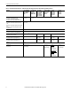
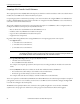
CompactLogix Controllers Specifications
Module width 100.00 mm
(3.94 in.)
1769-L24ER-QB1B = 115.00 mm (4.53 in.)
1769-L24ER-QBFC1B and 1769-L27ERM-QBFC1B =
140 mm (5.51 in.)
55.00 mm
(2.17 in.)
Module location DIN rail mount DIN rail or panel mount
Panel-mounting screw torque N/A 1.1…1.8 N
m (10…16 lbin) - use M4 or #8 screws
Embedded power supply 24V DC input, isolated 24V DC Input, isolated 1769-PA2, 1769-PB2, 1769-PA4, 1769-PB4
Power supply distance rating NA • Controller and 1769-SDN: 4
• 1769 Compact I/O modules: 4…8, depending on
module
Wire category
(2)
1 - signal ports
1 - power ports
2 - communication ports
2 - communication ports
Wire type, Ethernet RJ-45 connector according to IEC 60603-7, 2 or 4 pair Category 5e minimum cable according to TIA 568-B.1 or Category 5 cable according to ISO/IEC 24702
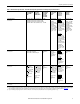
Wire type, power terminals and
embedded I/O connections
Copper N/A
Wire size, power terminals
(3)
0.051…3.31 mm
2
(30…12 AWG) solid or stranded
copper wire rated at 75 °C (167 °F), or greater,
1.2 mm (3/64 in.) insulation, max
Each terminal accepts 1 or 2 wires
0.25…2.50 mm
2
(22…14 AWG) solid copper wire
rated at 75 °C (167 °F), or greater
1.2 mm (3/64 in.) insulation, max
Each terminal accepts only 1 wire
N/A
Wire stripping length,
power terminals
(3)
10 mm (0.39 in) 8 mm (0.31 in) N/A
Screw torque, power terminals
(3)
0.5…0.6 N•m (4.4…5.3 lb•in) 1.0…1.2 N•m (8.9…10.6 lb•in) N/A
Wire size, embedded I/O
connections
0.205…1.31 mm
2
(24…16 AWG) solid or stranded copper wire rated at 75 °C (167 °F), or greater
1.2 mm (3/64 in.) insulation, max or 90 °C (194 °F)
Each terminal accepts only 1 wire
N/A
Wire stripping length, embedded
I/O connections
10 mm (0.39 in) N/A
North American temperature code T4A T3C T5
IEC temperature code T4 T5
Enclosure type rating None (open-style)
(1) You can use up to the maximum number of local expansion modules with the CompactLogix 5370 L1 controllers listed as long as the total current drawn by the embedded I/O and local expansion modules
does not exceed both the available POINTBus backplane current of 1 A and the field power current of 3 A. For more information on POINTBus backplane current and field power current considerations
when installing local expansion modules, see page 9
.
(2) Use this Conductor Category information for planning conductor routing. Refer to Industrial Automation Wiring and Grounding Guidelines, publication 1770-4.1
and the appropriate system-level
installation manual.
(3) With respect to the CompactLogix 5370 L1 controllers, this specification applies to connecting wires to the power connector that is inserted in the controller. With respect to the CompactLogix 5370 L2
controllers, this specification applies to connecting wires to power terminals built into the controller.
Table 3 - Technical Specifications - CompactLogix 5370 Controllers
Attribute 1769-L16ER-BB1B, 1769-L18ER-BB1B,
1769-L18ERM-BB1B
1769-L24ER-QB1B, 1769-L24ER-QBFC1B,
1769-L27ERM-QBFC1B
1769-L30ER, 1769-L30ER-NSE, 1769-L30ERM,
1769-L33ER, 1769-L33ERM, 1769-L36ERM