Installation Instructions Compact™ Individually Isolated AC/DC Relay Output Module (Catalog Number 1769-OW8I, Series B) Inside Module Description ................................................................................. 2 Module Installation.................................................................................. 3 System Assembly..................................................................................... 4 Mounting Expansion I/O .................................................
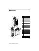
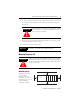
Compact™ Individually Isolated AC/DC Relay Output Module Module Description 1 2a Item Description 1 bus lever (with locking function) 2a upper panel mounting tab 2b lower panel mounting tab 3 I/O diagnostic LEDs 4 module door with terminal identification label 5a movable bus connector with female pins 5b stationary bus connector with male pins 6 nameplate label 7a upper tongue-and-groove slots 7b lower tongue-and-groove slots 8a upper DIN rail latch 8b lower DIN rail latch 9
Compact™ Individually Isolated AC/DC Relay Output Module 3 Module Installation Compact I/O is suitable for use in an industrial environment when installed in accordance with these instructions. Specifically, this equipment is intended for use in clean, dry environments (Pollution degree 2(1)) and to circuits not exceeding Over Voltage Category II(2) (IEC 60664-1).
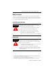
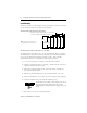
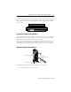
Compact™ Individually Isolated AC/DC Relay Output Module System Assembly The module can be attached to the controller or an adjacent I/O module before or after mounting. For mounting instructions, see "Panel Mounting" on page 6, or "DIN Rail Mounting" on page 7. To work with a system that is already mounted, see "Replacing a Single Module within a System" on page 7. The following procedure shows you how to assemble the Compact I/O system. 3 4 2 1 6 1 5 1. Disconnect power. 2.
Compact™ Individually Isolated AC/DC Relay Output Module 5 6. To allow communication between the controller and module, move the bus lever fully to the left (4) until it clicks. Ensure it locks firmly into the bus locking tab. ATTENTION When attaching I/O modules, it is very important that the bus connectors are securely locked together to ensure proper electrical connection. ! 7. Attach an end cap terminator (5) to the last module in the system by using the tongue-and-groove slots as before. 8.
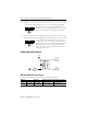
Compact™ Individually Isolated AC/DC Relay Output Module Panel Mounting Mount the module to a panel using two screws per module. Use M4 or #8 panhead screws. Mounting screws are required on every module. Panel Mounting Using the Dimensional Template End Cap Compact I/O 122.6±0.2 (4.826±0.008) 28.5 (1.12) 35 (1.38) Compact I/O Note: All dimensions are in mm (inches). Hole spacing tolerance: ±0.4 mm (0.016 in.). Compact I/O 132 (5.
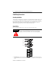
Compact™ Individually Isolated AC/DC Relay Output Module 7 DIN Rail Mounting The module can be mounted using the following DIN rails: 35 x 7.5 mm (EN 50 022 - 35 x 7.5) or 35 x 15 mm (EN 50 022 - 35 x 15). Before mounting the module on a DIN rail, close the DIN rail latches. Press the DIN rail mounting area of the module against the DIN rail. The latches will momentarily open and lock into place.
Compact™ Individually Isolated AC/DC Relay Output Module Field Wiring Connections Grounding the Module This product is intended to be mounted to a well-grounded mounting surface such as a metal panel. Additional grounding connections from the module’s mounting tabs or DIN rail (if used), are not required unless the mounting surface cannot be grounded. Refer to Industrial Automation Wiring and Grounding Guidelines, Allen-Bradley publication 1770-4.1, for additional information.
Compact™ Individually Isolated AC/DC Relay Output Module 9 A removable, write-on label is provided with the module. Remove the label from the door, mark the identification of each terminal with permanent ink, and slide the label back into the door. Your markings (ID tag) will be visible when the module door is closed. SLOT # _____ MODULE TYPE ______ Removing the Finger-Safe Terminal Block When wiring field devices to the module, it is not necessary to remove the terminal block.
Compact™ Individually Isolated AC/DC Relay Output Module 2. Route the wire under the terminal pressure plate. You can use the bare wire or a spade lug. The terminals will accept a 6.35 mm (0.25 in.) spade lug. TIP The terminal screws are non-captive. Therefore, it is possible to use a ring lug [maximum 1/4 inch o.d. with a 0.139 inch minimum i.d. (M3.5)] with the module. 3. Tighten the terminal screw making sure the pressure plate secures the wire.
Compact™ Individually Isolated AC/DC Relay Output Module 11 I/O Memory Mapping Output Data File Word For each module, slot x, word 0 in the output data file contains the control program’s directed state of the discrete output points. For the 1769-OW8I, bits 8 to 15 are not used.
Compact™ Individually Isolated AC/DC Relay Output Module 1769-OW8I Configuration File The read/writable configuration data file allows the setup of the hold last state and user-defined safe state conditions. Word The manipulation of the bits from this file is normally done with programming software (e.g. RSLogix 500, RSNetworx for DeviceNet, etc.) during initial configuration of the system. In that case, graphical screens are provided via the programmer to simplify configuration.
Compact™ Individually Isolated AC/DC Relay Output Module 13 Fault Value Word The fault value word, word 4, is used to program the fault state value (0=Off, 1=On). Each output is individually configurable for on or off.
Compact™ Individually Isolated AC/DC Relay Output Module Specifications General Specifications Specification Value Dimensions 118 mm (height) x 87 mm (depth) x 35 mm (width) height including mounting tabs is 138 mm 4.65 in. (height) x 3.43 in (depth) x 1.38 in (width) height including mounting tabs is 5.43 in. Approximate Shipping Weight (with carton) 290g (0.64 lbs.
Compact™ Individually Isolated AC/DC Relay Output Module 15 Output Specifications Specification 1769-OW8I Voltage Category AC/DC normally open relay Operating Voltage Range 5 to 265V ac 5 to 125V dc Number of Outputs 8 Isolated Groups 8 individually isolated outputs Bus Current Draw (max.) 125 mA at 5V dc (0.625W) 100 mA at 24V dc (2.4W) Heat Dissipation 2.83 Total Watts (The Watts per point, plus the minimum Watts, with all points energized.) Signal Delay (max.
Compact™ Individually Isolated AC/DC Relay Output Module Relay Contact Ratings Volts (max.) Continuous Amps per Point (max.) 240V ac 2.5A 120V ac Amperes(1) Voltamperes Make Break Make Break 7.5A 0.75A 1800 VA 180 VA 15A 1.5A NEMA ICS 2-125 C300 125V dc 1.0A 0.22A(2) 28 VA R150 24V dc 2.0A 1.2A(2) 28 VA — (1) (2) Surge Suppression - Connecting surge suppressors across your external inductive load will extend the life of the relay contacts.
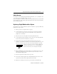
Compact™ Individually Isolated AC/DC Relay Output Module 17 Hazardous Location Considerations This equipment is suitable for use in Class I, Division 2, Groups A, B, C, D or non-hazardous locations only. The following WARNING statement applies to use in hazardous locations. WARNING ! EXPLOSION HAZARD • Substitution of components may impair suitability for Class I, Division 2. • Do not replace components or disconnect equipment unless power has been switched off or the area is known to be non-hazardous.
Compact™ Individually Isolated AC/DC Relay Output Module For More Information For Refer to this Document Pub. No. A more detailed description of how to install MicroLogix 1200 & 1500 and use your Compact™ I/O with MicroLogix™ Programmable Controllers User 1200 & 1500 programmable controller. Manual 1764-UM001B-US-P A more detailed description of how to install 1769-ADN DeviceNet Adapter User and use your Compact I/O with the 1769-ADN Manual DeviceNet Adapter.
Compact™ Individually Isolated AC/DC Relay Output Module 19 Publication 1769-IN053A-EN-P - April 2001
Compact, MicroLogix, CompactLogix, RSLogix and RSNetworx are trademarks of Rockwell Automation. DeviceNet is a trademark of Open DeviceNet Vendor Association (ODVA). Publication 1769-IN053A-EN-P - April 2001 Supersedes Publication 1769-IN005C-EN-P - June 2000 PN 40072-116-01 (A) © 2001 Rockwell International Corporation. Printed in the U.S.A.