Installation Instructions Compact TTL Output Module Catalog Number 1769-OG16 Topic Page About This Publication 1 Important User Information 2 About the 1769-OG16 Module 5 Install the 1769-OG16 Module 6 Replace a Single Module Within a System 7 Mount Expansion I/O 8 Mount Module to Panel 8 Mount Module to DIN Rail 10 Wire the 1769-OG16 Module 10 Ground the 1769-OG16 Module 12 Remove the Finger-safe Terminal Block 12 Wire the Finger-safe Terminal Block 13 Configure the 1769-OG16 Mo
Compact TTL Output Module Important User Information Solid state equipment has operational characteristics differing from those of electromechanical equipment. Safety Guidelines for the Application, Installation and Maintenance of Solid State Controls (publication SGI-1.1 available from your local Rockwell Automation sales office or online at http://literature.rockwellautomation.com) describes some important differences between solid state equipment and hard-wired electromechanical devices.
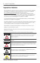
Compact TTL Output Module 3 Prevent Electrostatic Discharge ATTENTION Electrostatic discharge can damage integrated circuits or semiconductors if you touch bus connector pins. Follow these guidelines when you handle the module: – Touch a grounded object to discharge static potential. – Wear an approved wrist-strap grounding device. – Do not touch the bus connector or connector pins. – Do not touch circuit components inside the module. – If available, use a static-safe work station.
Compact TTL Output Module Hazardous Location Considerations This equipment is suitable for use in Class I, Division 2, Groups A, B, C, D or nonhazardous locations only. The following WARNING statement applies to use in hazardous locations. WARNING Explosion Hazard • Substitution of components may impair suitability for Class I, Division 2. • Do not replace components or disconnect equipment unless power is switched off or the area is known to be nonhazardous.
Compact TTL Output Module 5 About the 1769-OG16 Module Compact I/O is suitable for use in an industrial environment when installed in accordance with these instructions. Specifically, this equipment is intended for use in clean, dry environments (Pollution degree 2(1)) and to circuits not exceeding Over Voltage Category II(2) (IEC 60664-1)(3).
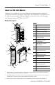
Compact TTL Output Module Install the 1769-OG16 Module Attach the module to the controller or an adjacent I/O module before or after mounting. For mounting instructions, see Mount Module to Panel Using the Dimensional Template, or Mount Module to DIN Rail. To work with a system that is already mounted, see Replace a Single Module Within a System. The following procedure shows you how to assemble the Compact I/O system. 3 4 2 1 6 1 5 30536-M 1. Disconnect power. 2.
Compact TTL Output Module 7 6. To allow communication between the controller and module, move the bus lever fully to the left (4) until it clicks, making sure it is locked firmly in place. ATTENTION When attaching I/O modules, it is very important that the bus connectors are securely locked together to be sure of proper electrical connection. 7. Attach an end-cap terminator (5) to the last module in the system by using the tongue-and-groove slots as before. 8. Lock the end-cap bus terminator (6).
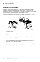
Compact TTL Output Module 6. Be sure that the bus lever on the module and on the right-side adjacent module are in the unlocked (fully right) position before installing the replacement module. 7. Slide the replacement module into the open slot. 8. Connect the modules by locking (fully left) the bus levers on the replacement module and the right-side adjacent module. 9. Replace the mounting screws (or snap the module onto the DIN rail).
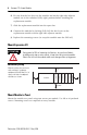
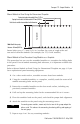
Compact TTL Output Module 9 Mount Module to Panel Using the Dimensional Template Host Controller Spacing for single-wide modules 35mm (1.378 in.) Spacing for one-and-a half-wide modules 52.5mm (2.067 in.) Refer to host controller documentation for this dimension. Note: Overall hole spacing tolerance: ±0.4mm (0.016 in.). Locate holes every 17.5 mm (0.689 in.) to allow for a mix of single-wide and one-and-a-half-wide modules (for example, the 1769-OA16 module).
Compact TTL Output Module Mount Module to DIN Rail The module can be mounted using these DIN rails. • 35 x 7.5 mm (EN 50 022 - 35 x 7.5) • 35 x 15 mm (EN 50 022 - 35 x 15) Before mounting the module on a DIN rail, close the DIN-rail latches. Press the DIN-rail mounting area of the module against the DIN rail. The latches will momentarily open and lock into place. Wire the 1769-OG16 Module Each terminal accepts as many as two wires with these restrictions.
Compact TTL Output Module 11 Output Wiring General Notes: 1. Use Belden 8761, or equivalent, shielded wire. 2. Do not connect more than 2 wires to any single terminal. 3. DC power cable and I/O cables should not exceed 30 ft (10 m) in length. 4. The capacitors shown above must be 0.01uF and rated for 2000 volts (minimum). 5. User power supply must be rated Class 2 with a 5V dc range of 4.5V to 5.5V dc.
Compact TTL Output Module Ground the 1769-OG16 Module This product is intended to be mounted to a well-grounded mounting surface such as a metal panel. Additional grounding connections from the module’s mounting tabs or DIN rail (if used) are not required unless the mounting surface cannot be grounded. Refer to Industrial Automation Wiring and Grounding Guidelines, Allen-Bradley publication 1770-4.1, for additional information. A removable, write-on label is provided with the module.
Compact TTL Output Module 13 Wire the Finger-safe Terminal Block When wiring the terminal block, keep the finger-safe cover in place. 1. Loosen the terminal screws to be wired. 2. Route the wire under the terminal pressure plate. You can use the bare wire or a spade lug. The terminals will accept a 6.35 mm (0.25 in.) spade lug. The terminal screws are non-captive. Therefore, it is possible to use a ring lug [max 1/4 in. o.d. with a 0.139 in. minimum i.d. (M3.5)] with the module. TIP 3.
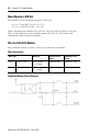
Compact TTL Output Module Input Data File For each module, slot x, word 0 in the input data file contains the state of the module’s output data file (output data echo). During normal operation, these input bits represent the logic state that the outputs are directed to by the control program. They are also dependent upon the: • Program mode configuration (if supported by the controller). • Fault mode configuration (if supported by the controller).
Compact TTL Output Module 15 Configuration File The read/writable configuration data file allows the setup of the hold last state and user-defined safe state conditions. The manipulation of the bits from this file is normally done with programming software (such as RSLogix 500 or RSNetworx for DeviceNet) during initial configuration of the system. In that case, graphical dialogs are provided via the programmer to simplify configuration.
Compact TTL Output Module Fault State Word Word 3, the fault state word, selects the hold last state or user-defined safe state condition for each individual output on a system transition from Run to Fault. Condition Bit Setting User-defined Safe State 0 Hold Last State 1 Fault Value Word(1) The fault value word, word 4, is used to program the fault state value (0 = Off, 1 = On). Each output is individually configurable for on or off.
Compact TTL Output Module 17 Specifications Compact TTL Output Module - 1769-OG16 Attribute Value Bus Current Draw, Max 200 mA at 5V dc Heat Dissipation 1.2 Total Watts (The Watts per point, plus the minimum Watts, with all points energized.) Power Supply Distance Rating 8 (The module may not be more than 8 modules away from the power supply or controller.) Vendor I.D.
Compact TTL Output Module Environmental Specifications Attribute Value Storage Temperature -40…+85 °C (-40…+185°F) Operating Temperature 0…60 °C (32…140 °F) Operating Humidity 5…95% non-condensing Operating Altitude 2000 m (6561 ft) Vibration Operating: 10…500 Hz, 5 g, 0.030 in.
Compact TTL Output Module 19 Additional Resources You can view or download publications at http://literature.rockwellautomation.com. To order paper copies of technical documentation, contact your local Rockwell Automation distributor or sales representative. Related Documentation For Refer to This Document Pub. No.
Rockwell Automation Support Rockwell Automation provides technical information on the web to assist you in using its products. At http://support.rockwellautomation.com, you can find technical manuals, a knowledge base of FAQs, technical and application notes, sample code and links to software service packs, and a MySupport feature that you can customize to make the best use of these tools.