Installation Instructions CompactLogix Analog Output Module Catalog Numbers 1769-OF8C, 1769-OF8V Topic Page About the Module 5 Assembling the Module 7 Mounting Expansion I/O 8 Replacing a Single Module within a System 10 Module Spare/replacement Parts 11 Grounding the Module 11 System Wiring Guidelines 12 I/O Memory Mapping 17 RSLogix 5000 Controller Tags 22 Specifications 32 Additional Resources 38
CompactLogix Analog Output Module Important User Information Solid-state equipment has operational characteristics differing from those of electromechanical equipment. Safety Guidelines for the Application, Installation and Maintenance of Solid State Controls (Publication SGI-1.1 available from your local Rockwell Automation sales office or online at http://www.rockwellautomation.com/literature/) describes some important differences between solid-state equipment and hard-wired electromechanical devices.
CompactLogix Analog Output Module 3 North American Hazardous Location Approval The following information applies when operating this equipment in hazardous locations. Informations sur l’utilisation de cet équipement en environnements dangereux. Products marked "CL I, DIV 2, GP A, B, C, D" are suitable for use in Class I Division 2 Groups A, B, C, D, Hazardous Locations and nonhazardous locations only.
CompactLogix Analog Output Module Environment and Enclosure ATTENTION: This equipment is intended for use in a Pollution Degree 2 industrial environment, in overvoltage Category II applications (as defined in IEC 60664-1), at altitudes up to 2000 m (6562 ft) without derating. This equipment is considered Group 1, Class A industrial equipment according to IEC/CISPR 11.
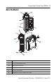
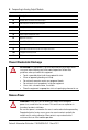
CompactLogix Analog Output Module 5 About the Module Item Description 1 Bus lever (with locking function) 2a Upper panel mounting tab 2b Lower panel mounting tab 3 Module status indicator 4 Module door with terminal identification label Rockwell Automation Publication 1769-IN089A-EN-P - March 2011
CompactLogix Analog Output Module Item Description 5a Movable bus connector with female pins 5b Stationary bus connector with male pins 6 Nameplate label 7a Upper tongue-and-groove slots 7b Lower tongue-and-groove slots 8a Upper DIN rail latch 8b Lower DIN rail latch 9 Write-on label (user ID tag) 10 Removable terminal block (RTB) with finger-safe cover 10a RTB upper retaining screw 10b RTB lower retaining screw Prevent Electrostatic Discharge ATTENTION: This equipment is sensitive
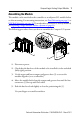
CompactLogix Analog Output Module 7 Assembling the Module The module can be attached to the controller or an adjacent I/O module before or after mounting. For mounting instructions, see Panel Mounting on page 9, or DIN Rail Mounting on page 10. To work with a system that is already mounted, see Replacing a Single Module within a System on page 10. The following procedure shows you how to assemble the Compact I/O system. 3 4 2 1 6 1 5 1. Disconnect power. 2.
CompactLogix Analog Output Module 6. To allow communication between the controller and module, move the bus lever fully to the left (4) until it clicks. Be sure that it is locked firmly in place. ATTENTION: When attaching I/O modules, it is very important that the bus connectors are securely locked together to ensure proper electrical connection. 7. Attach an end cap terminator (5) to the last module in the system by using the tongue-and-groove slots as before. 8. Lock the end cap bus terminator (6).
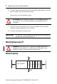
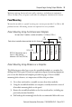
CompactLogix Analog Output Module 9 Maintain spacing from enclosure walls, wireways, and adjacent equipment. Allow 50 mm (2 in.) of space on all sides for adequate ventilation, as shown. Panel Mounting Mount the module to a panel by using two screws per module. Use M4 or #8 panhead screws. Mounting screws are required on every module. Panel Mounting Using the Dimensional Template 28.5 (1.12) End Cap Compact I/O Compact I/O 122.6±0.2 Compact I/O 132 (5.197) NOTE: All dimensions are in mm (in.).
CompactLogix Analog Output Module 5. Place the modules back on the panel, and check for proper hole alignment. 6. Attach the modules to the panel by using the mounting screws. TIP If mounting more modules, mount only the last one of this group and put the others aside. This reduces remounting time during drilling and tapping of the next group. 7. Repeat steps 1…6 for any remaining modules.
CompactLogix Analog Output Module 11 4. On the right-side adjacent module, move its bus lever to the right (unlock) to disconnect it from the module to be removed. 5. Gently slide the disconnected module forward. If you feel excessive resistance, check that the module has been disconnected from the bus, and that both mounting screws have been removed (or DIN latches opened).
CompactLogix Analog Output Module System Wiring Guidelines WARNING: EXPLOSION HAZARD All wiring must comply with N.E.C. article 501-4(b). Consider the following when wiring your system: • All module commons (ANLG COM) are connected in the analog module. The analog common (ANLG COM) is not connected to earth ground inside the module. • Channels are not isolated from each other. • Use Belden 8761, or equivalent, shielded wire.
CompactLogix Analog Output Module 13 External Power Switch The modules have an external 24V DC power switch that gives you the option of using an external power supply. The switch is located in on the lower left portion of the module’s circuit board, as shown below. With this switch pressed on the top (default), 24V DC power is drawn from the 1769 system power supply via the 1769 I/O bus. Pressed on the bottom, 24V DC power is drawn from the external power supply.
CompactLogix Analog Output Module Wiring Output Devices Basic wiring of output devices is shown below. ATTENTION: Miswiring of the module to an AC/DC source will damage the module. Be careful when stripping wires. Wire fragments that fall into a module could cause damage at power up. Once wiring is complete, make sure the module is free of all metal fragments.
CompactLogix Analog Output Module 15 • 1769-OF8V module: Labeling the Terminals A removable, write-on label is provided with the module. Remove the label from the door, mark the identification of each terminal with permanent ink, and slide the label back into the door. Your markings (ID tag) will be visible when the module door is closed.
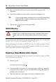
CompactLogix Analog Output Module Removing the Finger-Safe Terminal Block WARNING: When you connect or disconnect the Removable Terminal Block (RTB) with field side power applied, an electrical arc can occur. This could cause an explosion in hazardous location installations. Be sure that power is removed or the area is nonhazardous before proceeding. To remove the terminal block, loosen the upper and lower retaining screws. The terminal block will back away from the module as you remove the screws.
CompactLogix Analog Output Module 17 3. Tighten the terminal screw making sure the pressure plate secures the wire. Recommended torque when tightening terminal screws is 0.68 N•m (6 in•lb). If you need to remove the finger-safe cover, insert a screw driver into one of the square, wiring holes and gently pry the cover off. If you wire the terminal block with the finger-safe cover removed, you will not be able to put the cover back on the terminal block because the wires will obstruct the cover.
CompactLogix Analog Output Module Word Bit Position 15 14 13 12 11 10 9 8 7 6 5 4 3 2 1 0 2 SGN Analog Output Data Channel 2 3 SGN Analog Output Data Channel 3 4 SGN Analog Output Data Channel 4 5 SGN Analog Output Data Channel 5 6 SGN Analog Output Data Channel 6 7 SGN Analog Output Data Channel 7 8 UU7 UO7 UU6 UO6 UU5 UO5 UU4 UO4 UU3 UO3 UU2 UO2 UU1 UO1 UU0 UO0 • SGN = Sign bit in two’s complement format. • UU = Unlatch under-range (or low clamp exceeded) alarm.
CompactLogix Analog Output Module 19 • PF = Analog power fail. • S = General status (over-range, under-range, or open-circuit). • D = Open-circuit diagnostics. • H = Output held bit. • U = Under-range (or low-clamp exceeded) alarm. • O = Over-range (or high-clamp exceeded) alarm IMPORTANT The output module’s input data file reflects the analog output data echo of the module, not necessarily the electrical state of the output terminals. It does not reflect shorted or open outputs.
CompactLogix Analog Output Module Word Description Word Description 7 Channel 0 Spare 31 Channel 3 Spare 8 Channel 1 Configuration Word 0 32 Channel 4 Configuration Word 0 9 Channel 1 Configuration Word 1 33 Channel 4 Configuration Word 1 10 Channel 1 Fault Value Word 34 Channel 4 Fault Value Word 11 Channel 1 Program Idle Mode Word 35 Channel 4 Program Idle Mode Word 12 Channel 1 Low Clamp 36 Channel 4 Low Clamp 13 Channel 1 High Clamp 37 Channel 4 High Clamp 14 Channel
CompactLogix Analog Output Module 21 Word/Bit 15 14 Word 0 E Reserved 13 Word 1 Reserved 12 11 10 9 8 Output Data Format Select 7 6 5 4 3 2 1 0 SIU SIO LA ER FM PM HI PFE Reserved Output Type/Range • E = Channel Enable: (0 = Disabled, 1 = output 0 and hold Enabled, process changes) • Reserved = Set to zero • SIU = System interrupt low clamp, under-range alarms: (0 = Disabled, 1 = Enabled) • SIO = System interrupt high clamp, over-range alarms: (0 = Disabled, 1 = Enabled) • L
CompactLogix Analog Output Module Define Indicate this These bit settings 15 14 13 12 11 10 9 8 7 6 5 4 3 2 Program (Idle) Mode Hold Last State(1) 0 0 0 0 0 0 0 0 0 User-Defined Value(1) 0 0 0 0 0 0 0 0 1 Fault Mode Hold Last State(1) 0 0 0 0 0 0 0 0 0 User-Defined Fault Value(1) 0 0 0 0 0 0 0 0 1 Enable Ramping Disabled 0 0 0 0 0 0 0 0 Enabled 0 0 0 0 0 0 0 0 System Interrupt High Clamp Disabled 0 0 0 0 0 0 0 0 Enable
CompactLogix Analog Output Module 23 Channel 0 and 1 Configuration Data The following table lists channel 0 and 1 configuration data. The same information applies to all channels. - Local:1:C AB:1769_OF8C:C:0 Local:1:C.Ch0ProgToFaultEn BOOL Local:1:C.Ch0HoldForInit BOOL Decimal Decimal Local:1:C.Ch0ProgMode BOOL Decimal Local:1:C.Ch0FaultMode BOOL Decimal Local:1:C.Ch0RampEn BOOL Decimal Local:1:C.Ch0AlarmLatchEn BOOL Decimal Local:1:C.Ch0OverRangeInterruptEn BOOL Decimal Local:1:C.
CompactLogix Analog Output Module Local:1:C.Ch1En BOOL Decimal + Local:1:C.Ch1Range SINT Decimal + Local:1:C.Ch1DataFormat SINT Decimal + Local:1:C.Ch1FaultValue INT Decimal + Local:1:C.Ch1ProgValue INT Decimal + Local:1:C.Ch1LClampValue INT Decimal + Local:1:C.Ch1HClampValue INT Decimal + Local:1:C.
CompactLogix Analog Output Module 25 Tag Name To Select 15-8 Ch#DataFormat (1) 7 Make These Bit Settings(1) 6 5 4 3 2 Raw/proportional counts Engineering units Scaled for PID Percent range 1 0 0 0 0 1 1 1 0 1 All bit positions left blank in table must be set to 0.
CompactLogix Analog Output Module 1769-OF8C Input Data - Local:1:I AB:1769_OF8C:I:0 + Local:1:I.Fault DINT Binary + Local:1:I.CombinedStatus SINT Binary Local:1:I.Ch0Status BOOL Decimal Local:1:I.Ch1Status BOOL Decimal Local:1:I.Ch2Status BOOL Decimal Local:1:I.Ch3Status BOOL Decimal Local:1:I.Ch4Status BOOL Decimal Local:1:I.Ch5Status BOOL Decimal Local:1:I.Ch6Status BOOL Decimal Local:1:I.Ch7Status BOOL Decimal Local:1:I.ModuleStatus SINT Binary Local:1:I.
CompactLogix Analog Output Module 27 1769-OF8C Input Data + + Local:1:I.Ch3InHold BOOL Decimal Local:1:I.Ch3OpenWire BOOL Decimal Local:1:I.Ch4_5Status SINT Binary Local:1:I.Ch4OverRange BOOL Decimal Local:1:I.Ch4UnderRange BOOL Decimal Local:1:I.Ch4InHold BOOL Decimal Local:1:I.Ch4OpenWire BOOL Decimal Local:1:I.Ch5OverRange BOOL Decimal Local:1:I.Ch5UnderRange BOOL Decimal Local:1:I.Ch5InHold BOOL Decimal Local:1:I.Ch5OpenWire BOOL Decimal Local:1:I.
CompactLogix Analog Output Module 1769-OF8V Input Data Tag Name Bit Indicates This(1) Combined Status Ch7 Status 7 6 Ch6 Status 5 Ch5 Status 4 Ch4 Status 3 Ch3 Status 2 Ch2 Status 1 Ch1 Status Module Status 0 Ch0 Status Power Fail Ch0_1 Status Ch1 InHold Ch1 Under Range Ch1 Over Range Ch0 InHold Ch0 Under Range Ch0 Over Range Ch2_3 Status Ch3 InHold Ch3 Under Range Ch3 Over Range Ch2 InHold Ch2 Under Range Ch2 Over Range Ch4_5 Status Ch5 InHold Ch5 Under Range Ch5 Over Range
CompactLogix Analog Output Module 29 1769-OF8V Input Data - Local:1:I AB:1769_OF8V:I:0 + Local:1:I.Fault DINT Binary + Local:1:I.CombinedStatus SINT Binary Local:1:I.Ch0Status BOOL Decimal Local:1:I.Ch1Status BOOL Decimal Local:1:I.Ch2Status BOOL Decimal Local:1:I.Ch3Status BOOL Decimal Local:1:I.Ch4Status BOOL Decimal Local:1:I.Ch5Status BOOL Decimal Local:1:I.Ch6Status BOOL Decimal Local:1:I.Ch7Status BOOL Decimal Local:1:I.ModuleStatus SINT Binary Local:1:I.
CompactLogix Analog Output Module 1769-OF8V Input Data + + Local:1:I.Ch4_5Status SINT Local:1:I.Ch4OverRange BOOL Binary Decimal Local:1:I.Ch4UnderRange BOOL Decimal Local:1:I.Ch4InHold BOOL Decimal Local:1:I.Ch5OverRange BOOL Decimal Local:1:I.Ch5UnderRange BOOL Decimal Local:1:I.Ch5InHold BOOL Decimal Local:1:I.Ch6_7Status SINT Binary Local:1:I.Ch6OverRange BOOL Decimal Local:1:I.Ch6UnderRange BOOL Decimal Local:1:I.Ch6InHold BOOL Decimal Local:1:I.
CompactLogix Analog Output Module 31 Output Data 1769-OF8C and 1769-OF8V Output Data Local:1:O AB:1769_OF8C:O:0 / AB:1769_OF8V:O:0 + Local:1:O.Ch0Data INT Decimal + Local:1:O.Ch1Data INT Decimal + Local:1:O.Ch2Data INT Decimal + Local:1:O.Ch3Data INT Decimal + Local:1:O.Ch4Data INT Decimal + Local:1:O.Ch5Data INT Decimal + Local:1:O.Ch6Data INT Decimal + Local:1:O.Ch7Data INT Decimal + Local:1:O.AlarmUnlatch INT Binary Local:1:O.
CompactLogix Analog Output Module Specifications General Specifications 1769-OF8C and 1768-OF8V Attribute 1769-OF8C and 1768-OF8V Dimensions, HxWxD (approx.) 118 mm x 35 mm x 87 mm Height including mounting tabs is 138 mm 4.65 in. x 1.38 in. x 3.43 in. Height including mounting tabs is 5.43 in. Approximate Shipping Weight (with carton) 281g (0.62 lb.) Enclosure type rating None (open-style) Wire Size 0.32…2.1 mm2 (22…14 AWG) solid copper wire or 0.32…1.
CompactLogix Analog Output Module 33 Environmental Specifications 1769-OF8C and 1769-OF8V Attribute 1769-OF8C and 1769-OF8V Shock, operating IEC 60068-2-27 (Test Ea, Unpackaged Shock) 20 g Shock, nonoperating IEC 60068-2-27 (Test Ea, Unpackaged Shock) 30 g Relative humidity IEC 60068-2-30 (Test Db, Unpackaged Damp Heat) 5…95% noncondensing Emissions CISPR 11: Group 1, Class A ESD immunity IEC 61000-4-2 4 kV contact discharges 8 kV air discharges Radiated RF immunity IEC 61000-4-3 10V/m with 1 k
CompactLogix Analog Output Module Output Specifications 1769-OF8C and 1769-OF8V Attribute 1769-OF8C and 1769-OF8V Analog normal operating ranges(1) (1769-OF8C): 0…20 mA, 4…20 mA (1769-OF8V): ± 10V dc, 0…10V DC, 0…5V DC, 1…5V DC Full Scale analog ranges(1) (1769-OF8C): 0…21 mA, 3.2 to 21 mA (1769-OF8V): ± 10.5V dc, -0.5…10.5V DC, -0.5…5.25V DC, 0.5…5.
CompactLogix Analog Output Module 35 Output Specifications 1769-OF8C and 1769-OF8V Attribute 1769-OF8C and 1769-OF8V Non-linearity (in percent full scale) ±0.05% Repeatability(6) (in percent full scale) ±0.05% Output error over full temperature Range (0…60 °C [+32…+140 °F]) (1769-OF8C) Current: ±0.55% (1769-OF8V) Current:±0.80% Output offset error (0…60 °C [+32…+140 °F]) ±0.
CompactLogix Analog Output Module Output Specifications 1769-OF8C and 1769-OF8V Attribute 1769-OF8C and 1769-OF8V Output words 9 Configuration words 64 (1) The over- or under-range flag will come on when the normal operating range (over/under) is exceeded. The module will continue to convert the analog input up to the maximum full scale range. The flag automatically resets when within the normal operating range unless configured to latch.
CompactLogix Analog Output Module 37 Certifications Certifications(1) (when product is marked) 1769-OF8C and 1769-OF8V c-UL-us UL Listed for Class I, Division 2 Group A,B,C,D Hazardous Locations, certified for U.S. and Canada. See UL File E10314.
CompactLogix Analog Output Module Additional Resources These documents contain additional information concerning related Rockwell Automation products. Resource Description 1769-L32E and 1769-L35E CompactLogix Controller Installation Instructions, publication 1769-IN020 Provides details about how to assemble and mount the controller, how to upgrade firmware, and controller technical specifications.
CompactLogix Analog Output Module 39 Notes: Rockwell Automation Publication 1769-IN089A-EN-P - March 2011
Rockwell Automation Support Rockwell Automation provides technical information on the Web to assist you in using its products. At http://www.rockwellautomation.com/support/, you can find technical manuals, a knowledge base of FAQs, technical and application notes, sample code and links to software service packs, and a MySupport feature that you can customize to make the best use of these tools.