Installation Instructions Compact 1769-OF8V Analog Output Module Inside Module Description ..................................................................................2 Module Installation...................................................................................3 System Assembly......................................................................................4 Mounting Expansion I/O ...........................................................................
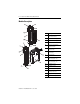
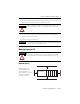
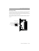
Compact 1769-OF8V Analog Output Module Module Description Item Description Publication 1769-IN066D-EN-P - June 2010 1 bus lever (with locking function) 2a upper panel mounting tab 2b lower panel mounting tab 3 module status LED 4 module door with terminal identification label 5a movable bus connector with female pins 5b stationary bus connector with male pins 6 nameplate label 7a upper tongue-and-groove slots 7b lower tongue-and-groove slots 8a upper DIN rail latch 8b lower DIN
Compact 1769-OF8V Analog Output Module 3 Module Installation Compact I/O is suitable for use in an industrial environment when installed in accordance with these instructions. Specifically, this equipment is intended for use in clean, dry environments (Pollution degree 2(1)) and to circuits not exceeding Over Voltage Category II(2) (IEC 60664-1).
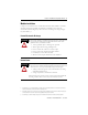
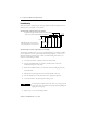
Compact 1769-OF8V Analog Output Module System Assembly The module can be attached to the controller or an adjacent I/O module before or after mounting. For mounting instructions, see “Panel Mounting” on page 6, or “DIN Rail Mounting” on page 7. To work with a system that is already mounted, see “Replacing a Single Module within a System” on page 7. The following procedure shows you how to assemble the Compact I/O system. 3 4 2 1 6 1 5 1. Disconnect power. 2.
Compact 1769-OF8V Analog Output Module 5 6. To allow communication between the controller and module, move the bus lever fully to the left (4) until it clicks. Ensure it is locked firmly in place. ATTENTION When attaching I/O modules, it is very important that the bus connectors are securely locked together to ensure proper electrical connection. 7. Attach an end cap terminator (5) to the last module in the system by using the tongue-and-groove slots as before. 8. Lock the end cap bus terminator (6).
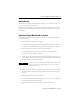
Compact 1769-OF8V Analog Output Module Panel Mounting Mount the module to a panel using two screws per module. Use M4 or #8 panhead screws. Mounting screws are required on every module. Panel Mounting Using the Dimensional Template End Cap Compact I/O 122.6±0.2 (4.826±0.008) 28.5 (1.12) Compact I/O NOTE: All dimensions are in mm (inches). Hole spacing tolerance: ±0.4 mm (0.016 in.) Compact I/O 132 (5.197) Host Controller For more than 2 modules: (number of modules-1) X 35mm (1.38 in.
Compact 1769-OF8V Analog Output Module 7 DIN Rail Mounting The module can be mounted using the following DIN rails: 35 x 7.5 mm (EN 50 022 - 35 x 7.5) or 35 x 15 mm (EN 50 022 - 35 x 15). Before mounting the module on a DIN rail, close the DIN rail latches. Press the DIN rail mounting area of the module against the DIN rail. The latches will momentarily open and lock into place. Replacing a Single Module within a System The module can be replaced while the system is mounted to a panel (or DIN rail).
Compact 1769-OF8V Analog Output Module Module Spare/Replacement Parts • Terminal block, catalog number 1769-RTBN12 (1 per kit) (A-B part number A22112-319-01) • Door, catalog number 1769-RD (2 per kit) Field Wiring Connections Grounding the Module This product is intended to be mounted to a well-grounded mounting surface such as a metal panel. Additional grounding connections from the module’s mounting tabs or DIN rail (if used), are not required unless the mounting surface cannot be grounded.
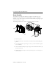
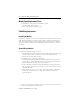
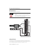
Compact 1769-OF8V Analog Output Module 9 External Power Switch The 1769-OF8V has an external 24V dc power switch which gives you the option of using an external power supply. The switch is located in on the lower left portion of the module’s circuit board, as shown below. With this switch pressed on the top (default), 24V dc power is drawn from the 1769 system power supply via the 1769 I/O bus. Pressed on the bottom, 24V dc power is drawn from the external power supply.
Compact 1769-OF8V Analog Output Module Wiring Output Devices Basic wiring of output devices is shown below. ATTENTION • Miswiring of the module to an AC/DC source will damage the module. • Be careful when stripping wires. Wire fragments that fall into a module could cause damage at power up. Once wiring is complete, ensure the module is free of all metal fragments. Labeling the Terminals A removable, write-on label is provided with the module.
Compact 1769-OF8V Analog Output Module 11 Removing the Finger-Safe Terminal Block To remove the terminal block, loosen the upper and lower retaining screws. The terminal block will back away from the module as you remove the screws. When replacing the terminal block, torque the retaining screws to 0.46 Nm (4.1 in-lbs).
Compact 1769-OF8V Analog Output Module Wire Size and Terminal Screw Torque Each terminal accepts up to two wires with the following restrictions: Wire Type Wire Size Terminal Screw Torque Retaining Screw Torque Solid Cu-90°C (194°F) #14 to #22 AWG 0.68 Nm (6 in-lbs) 0.46 Nm (4.1 in-lbs) Stranded Cu-90°C (194°F) #16 to #22 AWG 0.68 Nm (6 in-lbs) 0.46 Nm (4.
Compact 1769-OF8V Analog Output Module 13 Input Data File For each module, slot x, input data file words 3-10 contain the state of the module’s output data (output data echo) file words 0-7. During normal operation, these input words represent the analog values that the outputs are directed to by the control program.
Compact 1769-OF8V Analog Output Module Configuration Data File The manipulation of the bits from this file is normally done with programming software (e.g. RSLogix 500, RSNetWorx for DeviceNet, etc.) during initial configuration of the system. In that case, graphical screens are provided by the programmer to simplify configuration. However, some systems, like the 1769-ADN DeviceNet Adapter, also allow the bits to be altered as part of the control program, using communication rungs.
Compact 1769-OF8V Analog Output Module Word Description Word Description 48 Channel 6 Configuration Word 0 56 Channel 7 Configuration Word 0 49 Channel 6 Configuration Word 1 57 Channel 7 Configuration Word 1 50 Channel 6 Fault Value Word 58 Channel 7 Fault Value Word 51 Channel 6 Program Idle Mode Word 59 Channel 7 Program Idle Mode Word 52 Channel 6 Low Clamp 60 Channel 7 Low Clamp 53 Channel 6 High Clamp 61 Channel 7 High Clamp 54 Channel 6 Ramp Rate 62 Channel 7 Ramp Rate
Compact 1769-OF8V Analog Output Module Channel Configuration Words The first two words of each eight word group in the configuration file allow you to change the parameters of each channel independently. For example, words 8 and 9 correspond to channel 1 while words 56 and 57 correspond to channel 7.
Compact 1769-OF8V Analog Output Module 17 RSLogix 5000, Version 15, Controller Tags Use the following controller tags with RSLogix 5000, version 15 and later. Channel 0 and 1 Configuration Data Channel 0 and 1 configuration data is shown below. The same information applies to all channels. - Local:1:C AB:1769_OF8V:C:0 Local:1:C.Ch0ProgToFaultEn BOOL Decimal Local:1:C.Ch0HoldForInit BOOL Decimal Local:1:C.Ch0ProgMode BOOL Decimal Local:1:C.Ch0FaultMode BOOL Decimal Local:1:C.
Compact 1769-OF8V Analog Output Module Local:1:C.Ch1En BOOL Decimal + Local:1:C.Ch1Range SINT Decimal + Local:1:C.Ch1DataFormat SINT Decimal + Local:1:C.Ch1FaultValue INT Decimal + Local:1:C.Ch1ProgValue INT Decimal + Local:1:C.Ch1LClampValue INT Decimal + Local:1:C.Ch1HClampValue INT Decimal + Local:1:C.
Compact 1769-OF8V Analog Output Module 19 Input Data - Local:1:I AB:1769_OF8V:I:0 + Local:1:I.Fault DINT Binary + Local:1:I.CombinedStatus SINT Binary Local:1:I.Ch0Status BOOL Decimal Local:1:I.Ch1Status BOOL Decimal Local:1:I.Ch2Status BOOL Decimal Local:1:I.Ch3Status BOOL Decimal Local:1:I.Ch4Status BOOL Decimal Local:1:I.Ch5Status BOOL Decimal Local:1:I.Ch6Status BOOL Decimal + + + Local:1:I.Ch7Status BOOL Decimal Local:1:I.ModuleStatus SINT Binary Local:1:I.
Compact 1769-OF8V Analog Output Module + Local:1:I.Ch4_5Status SINT Binary Local:1:I.Ch4OverRange BOOL Decimal Local:1:I.Ch4UnderRange BOOL Decimal Local:1:I.Ch4InHold BOOL Decimal Local:1:I.Ch5OverRange BOOL Decimal Local:1:I.Ch5UnderRange BOOL Decimal Local:1:I.Ch5InHold BOOL Decimal Local:1:I.Ch6_7Status SINT Binary Local:1:I.Ch6OverRange BOOL Decimal Local:1:I.Ch6UnderRange BOOL Decimal Local:1:I.Ch6InHold BOOL Decimal Local:1:I.
Compact 1769-OF8V Analog Output Module Tag Name Bit Indicates This(1) Combined Status Ch7 Status 7 6 Ch6 Status 5 Ch5 Status 4 Ch4 Status 3 Ch3 Status 2 Ch2 Status 1 Ch1 Status Module Status 21 0 Ch0 Status Power Fail Ch0_1 Status Ch1 InHold Ch1 Under Range Ch1 Over Range Ch0 InHold Ch0 Under Range Ch0 Over Range Ch2_3 Status Ch3 InHold Ch3 Under Range Ch3 Over Range Ch2 InHold Ch2 Under Range Ch2 Over Range Ch4_5 Status Ch5 InHold Ch5 Under Range Ch5 Over Range Ch4 InHold
Compact 1769-OF8V Analog Output Module Output Data Local:1:O AB:1769_OF8V:O:0 + Local:1:O.Ch0Data INT Decimal + Local:1:O.Ch1Data INT Decimal + Local:1:O.Ch2Data INT Decimal + Local:1:O.Ch3Data INT Decimal + Local:1:O.Ch4Data INT Decimal + Local:1:O.Ch5Data INT Decimal + Local:1:O.Ch6Data INT Decimal + Local:1:O.Ch7Data INT Decimal + Local:1:O.AlarmUnlatch INT Binary Local:1:O.Ch0OverRangeUnlatch BOOL Decimal Local:1:O.
Compact 1769-OF8V Analog Output Module 23 Specifications General Specifications Specification Value Dimensions 118 mm (height) x 87 mm (depth) x 35 mm (width) height including mounting tabs is 138 mm 4.65 in. (height) x 3.43 in (depth) x 1.38 in (width) height including mounting tabs is 5.43 in. Approximate Shipping Weight (with carton) 263g (0.58 lbs.
Compact 1769-OF8V Analog Output Module Output Specifications Specification 1769-OF8V Analog Normal Operating Ranges(1) ± 10V dc, 0 to 10V dc, 0 to 5V dc, 1 to 5V dc Full Scale Analog Ranges(1) ± 10.5V dc, -0.5 to 10.5V dc, -0.5 to 5.25V dc, 0.5 to 5.25V dc Number of Outputs 8 single-ended Bus Current Draw (max.) 145 mA at 5V dc 135 mA at 24V dc(2) Heat Dissipation 2.16 Total Watts (All points - 10.5V into 1 kΩ - worst case calculated.
Compact 1769-OF8V Analog Output Module Specification 1769-OF8V Accuracy Drift with Temperature ±0.0086% FS per °C Output Ripple range 0 to 50 kHz (referred to output range) ±0.05% Non-linearity (in percent full scale) ±0.05% Repeatability(2) ±0.05% (1) 25 (in percent full scale) Output Error Over Full Temperature Range (0 to 60°C [+32 to +140°F]) ±0.8% Output Offset Error (0 to 60°C [+32 to +140°F]) ±0.
Compact 1769-OF8V Analog Output Module Specification 1769-OF8V System Power Supply Distance Rating The module may not be more than 8 modules away from the system power supply. Optional 24V dc Class 2 Power 20.4 V to 26.4 V dc Supply Voltage Range(1) Recommended Cable Belden™ 8761 (shielded) Vendor I.D.
Compact 1769-OF8V Analog Output Module 27 Environnements dangereux Cet équipement est conçu pour être utilisé dans des environnements de Classe 1, Division 2, Groupes A, B, C, D ou non dangereux. La mise en garde suivante s’applique à une utilisation dans des environnements dangereux. ATTENTION DANGER D’EXPLOSION • La substitution de composants peut rendre cet équipement impropre à une utilisation en environnement de Classe 1, Division 2.
Compact 1769-OF8V Analog Output Module For More Information For Refer to this Document Pub. No. A more detailed description of how to install and MicroLogix 1500 Programmable Controllers User Manual use your Compact I/O with MicroLogix 1500 programmable controller. 1764-UM001A-US-P Detailed information on installing, programming, Compact I/O Analog Modules User Manual and troubleshooting your Compact Analog I/O modules.
Compact 1769-OF8V Analog Output Module 29 Notes: Publication 1769-IN066D-EN-P - June 2010
Compact 1769-OF8V Analog Output Module Notes: Publication 1769-IN066D-EN-P - June 2010
Compact 1769-OF8V Analog Output Module 31 Notes: Publication 1769-IN066D-EN-P - June 2010
Rockwell Automation Support Rockwell Automation provides technical information on the web to assist you in using our products. At http://support.rockwellautomation.com, you can find technical manuals, a knowledge base of FAQs, technical and application notes, sample code and links to software service packs, and a MySupport feature that you can customize to make the best use of these tools.