Installation Instructions Compact 1769-OF4VI Isolated Analog Output Module Catalog Number 1769-OF4VI Topic Page Important User Information 2 About the Module 4 System Assembly 6 Mounting Expansion I/O 8 Replacing a Single Module Within a System 11 Module Spare/replacement Parts 12 Grounding the Module 12 I/O Memory Mapping 17 Specifications 22 Additional Resources 27
Compact 1769-OF4VI Isolated Analog Output Module Important User Information Solid-state equipment has operational characteristics differing from those of electromechanical equipment. Safety Guidelines for the Application, Installation and Maintenance of Solid State Controls (Publication SGI-1.1 available from your local Rockwell Automation sales office or online at http://www.rockwellautomation.
Compact 1769-OF4VI Isolated Analog Output Module 3 North American Hazardous Location Approval The following information applies when operating this equipment in hazardous locations. Informations sur l’utilisation de cet équipement en environnements dangereux. Products marked "CL I, DIV 2, GP A, B, C, D" are suitable for use in Class I Division 2 Groups A, B, C, D, Hazardous Locations and nonhazardous locations only.
Compact 1769-OF4VI Isolated Analog Output Module About the Module Compact I/O is suitable for use in an industrial environment when installed in accordance with these instructions.
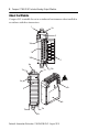
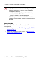
Compact 1769-OF4VI Isolated Analog Output Module 5 Item Description Item Description 1 Bus lever (with locking function) 7a Upper tongue-and-groove slots 2a Upper panel mounting tab 7b Lower tongue-and-groove slots 2b Lower panel mounting tab 8a Upper DIN rail latch 3 Module status LED 8b Lower DIN rail latch 4 Module door with terminal identification label 9 Write-on label (user ID tag) 5a Movable bus connector with female pins 10 Removable terminal block (RTB) with finger-safe
Compact 1769-OF4VI Isolated Analog Output Module ATTENTION: Remove power before removing or inserting this module. When you remove or insert a module with power applied, an electrical arc may occur. An electrical arc can cause personal injury or property damage by: • sending an erroneous signal to your system’s field devices, causing unintended machine motion. • causing an explosion in a hazardous environment. Electrical arcing causes excessive wear to contacts on both the module and its mating connector.
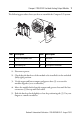
Compact 1769-OF4VI Isolated Analog Output Module 7 The following procedure shows you how to assemble the Compact I/O system. 3 4 2 1 6 1 5 Item Description Item Description 1 Tongue-and-groove slots 4 Bus lever 2 Bus connectors 5 End-cap terminator 3 Positioning tab 6 End-cap bus terminator 1. Disconnect power. 2. Check that the bus lever of the module to be installed is in the unlocked (fully right) position. 3.
Compact 1769-OF4VI Isolated Analog Output Module 6. To allow communication between the controller and module, move the bus lever fully to the left (4) until it clicks. Make sure it is locked firmly in place. ATTENTION: When attaching I/O modules, it is very important that the bus connectors are securely locked together to ensure proper electrical connection. 7. Attach an end-cap terminator (5) to the last module in the system by using the tongue-and-groove slots as before. 8.
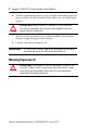
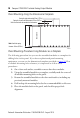
Compact 1769-OF4VI Isolated Analog Output Module 9 Minimum Spacing Maintain spacing from enclosure walls, wireways, and adjacent equipment. Allow 50 mm (2 in.) of space on all sides for adequate ventilation. 4 3 2 2 2 2 6 2 1 4 5 Item Description Item Description 1 Top 4 Side 2 Compact I/O modules 5 Bottom 3 End cap 6 Host controller Panel Mounting Mount the module to a panel using two screws per module. Use M4 or #8 panhead screws. Mounting screws are required on every module.
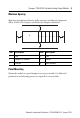
Compact 1769-OF4VI Isolated Analog Output Module Panel Mounting Using the Dimensional Template Host Controller Spacing for single-wide modules 35mm (1.378 in.) Spacing for one-and-a half-wide modules 52.5mm (2.067 in.) Refer to host controller documentation for this dimension. Note: Overall hole spacing tolerance: ±0.4mm (0.016 in.). 30535-M Panel Mounting Procedure Using Modules as a Template The following procedure lets you use the assembled modules as a template for drilling holes in the panel.
Compact 1769-OF4VI Isolated Analog Output Module 11 6. Attach the modules to the panel using the mounting screws. TIP If mounting more modules, mount only the last one of this group and put the others aside. This reduces remounting time during drilling and tapping of the next group. 7. Repeat steps 1 … 6 for any remaining modules. DIN Rail Mounting The module can be mounted using the following DIN rails. • 35 x 7.5 mm (1.38 x 0.30 in.; EN 50 022 - 35 x 7.5) • 35 x 15 mm (1.38 x 0.59 in.
Compact 1769-OF4VI Isolated Analog Output Module 5. Gently slide the disconnected module forward. If you feel excessive resistance, check that the module has been disconnected from the bus, and that both mounting screws have been removed (or DIN latches opened). TIP It may be necessary to rock the module slightly from front to back to remove it, or, in a panel-mounted system, to loosen the screws of adjacent modules. 6.
Compact 1769-OF4VI Isolated Analog Output Module 13 System Wiring Guidelines Consider the following when wiring your system: • Channels are isolated from each other. • Use Belden 8761, or equivalent, shielded wire. • Under normal conditions, the drain wire and shield junction must be connected to earth ground, via a panel or DIN rail mounting screw at the analog I/O module end. Keep the shield connection to ground as short as possible.
Compact 1769-OF4VI Isolated Analog Output Module Labeling the Terminals A removable, write-on label is provided with the module. Remove the label from the door, mark the identification of each terminal with permanent ink, and slide the label back into the door. Your markings (ID tag) will be visible when the module door is closed.
Compact 1769-OF4VI Isolated Analog Output Module 15 Removing the Finger-safe Terminal Block To remove the terminal block, loosen the upper and lower retaining screws. The terminal block will back away from the module as you remove the screws. When replacing the terminal block, torque the retaining screws to 0.46 N•m (4.1 in•lb).
Compact 1769-OF4VI Isolated Analog Output Module Wiring the Finger-safe Terminal Block When wiring the terminal block, keep the finger-safe cover in place. 1. Loosen the terminal screws to be wired. 2. Route the wire under the terminal pressure plate. You can use the bare wire or a spade lug. The terminals will accept a 6.35 mm (0.25 in.) spade lug. TIP The terminal screws are non-captive. You can use a ring lug [maximum 6.35 mm (0.25 in.) o.d. with a 3.53 mm (0.139 in.) minimum i.d. (M3.
Compact 1769-OF4VI Isolated Analog Output Module 17 Wire Size and Terminal Screw Torque Each terminal accepts up to two wires with the following restrictions: Wire Type Wire Size Terminal Screw Torque Retaining Screw Torque Cu-90 °C (194°F) #14…#22 AWG 0.68 N•m (6 in•lbs) 0.46 N•m (4.1 in-•bs) Stranded Cu-90 °C (194°F) #16…#22 AWG 0.68 N•m (6 in•lbs) 0.46 N•m (4.
Compact 1769-OF4VI Isolated Analog Output Module Input Data File Word For each module, slot x, input data file words 2…5 contain the state of the module’s output data (output data echo) file words 0…3. During normal operation, these input words represent the analog values that the outputs are directed to by the control program.
Compact 1769-OF4VI Isolated Analog Output Module 19 Configuration Data File The manipulation of the bits from this file is normally done with programming software (for example, RSLogix 500 software or RSNetworx for DeviceNet software) during initial configuration of the system. In that case, graphical screens are provided by the programmer to simplify configuration.
Compact 1769-OF4VI Isolated Analog Output Module Channel Configuration Words Word/Bit Word 0 Word 1 15 14 13 12 E 11 10 9 8 Reserved Reserved 7 6 5 SIU SIO LA Output Data Format Select 4 3 2 ER FM PM HI Reserved 0 1 PFE Output Type/Range • E = Channel Enable: (0 = Disabled, 1 = output Enabled, process changes) • Reserved = Set to zero • SIU = System interrupt low clamp, under-range alarms: (0 = Disabled, 1 = Enabled) • SIO = System interrupt high clamp, over-range alarms: (0 =
Compact 1769-OF4VI Isolated Analog Output Module 21 Define Indicate this These bit settings 15 14 13 12 11 10 9 8 7 6 5 4 3 2 Hold for Disabled Initialization Enabled Program (Idle) Mode Fault Mode Enable Ramping System Interrupt High Clamp System Interrupt Low Clamp Enable Channel (1) 1 0 0 1 Hold Last State(1) 0 User-Defined Value(1) 1 Hold Last State(1) 0 User-Defined Fault Value(1) 1 Disabled 0 Enabled 1 Disabled 0 Enabled(1) 1 Disabled 0 Enabled(1) 1 Disabled 0 En
Compact 1769-OF4VI Isolated Analog Output Module Specifications Specification 1769-OF4VI Dimensions 118 mm (height) x 87 mm (depth) x 35 mm (width) height including mounting tabs is 138 mm 4.65 in. (height) x 3.43 in (depth) x 1.38 in (width) height including mounting tabs is 5.43 in. Approximate Shipping Weight (with carton) 270g (0.6 lbs.
Compact 1769-OF4VI Isolated Analog Output Module 23 Specification 1769-OF4VI (2) Full Scale Analog Ranges ± 10.5V dc, -0.5 to 10.5V dc, -0.5 to 5.25V dc, 0.5 to 5.25V dc Number of Outputs 4 isolated differential Bus Current Draw (max.) 5V, 165mA 24V, 110mA Heat Dissipation 2.0 Total Watts (all points - 10V dc into 2 k - worst case calculated) Digital Resolution Across Full Range 15 bits plus sign (bipolar) ±10V dc: 15.89 bits, 330 µV/bit 0 to +5V dc: 13.89 bits, 330 µV/bit 0 to +10V dc: 14.
Compact 1769-OF4VI Isolated Analog Output Module Specification 1769-OF4VI Accuracy Drift with Temperature ±0.0086% FS per °C Output Ripple(1) range 0 to 50 kHz (referred to output range) ±0.05% Non-linearity (in percent full scale) ±0.05% Repeatability(2) (in percent full scale) ±0.05% Output Error Over Full Temperature Range (0 to 60°C [+32 to +140°F]) ±0.8% Output Impedance <1 Ω Open and Short-Circuit Protection Yes Short-Circuit Current 35 mA typical, 42 mA max.
Compact 1769-OF4VI Isolated Analog Output Module 25 Specification 1769-OF4VI System Power Supply Distance Rating The module may not be more than 8 modules away from the system power supply. Recommended Cable Belden 8761 (shielded) Vendor I.D. Code 1 Product Type Code 10 Product Code 42 Input Words 6 Output Words 5 Configuration Words 32 Hazardous Location Considerations This equipment is suitable for use in Class I, Division 2, Groups A, B, C, D or non-hazardous locations only.
Compact 1769-OF4VI Isolated Analog Output Module Environnements dangereux Cet équipement est conçu pour être utilisé dans des environnements de Classe 1, Division 2, Groupes A, B, C, D ou non dangereux. La mise en garde suivante s’applique à une utilisation dans des environnements dangereux. AVERTISSEMENT: DANGER D’EXPLOSION La substitution de composants peut rendre cet équipement impropre à une utilisation en environnement de Classe 1, Division 2.
Compact 1769-OF4VI Isolated Analog Output Module 27 Additional Resources These documents contain additional information concerning related Rockwell Automation products. Resource Description Compact I/O Analog Modules User Manual, publication 1769-UM002 Provides detailed information on installing, programming, and troubleshooting Compact analog I/O modules.
Rockwell Automation Support Rockwell Automation provides technical information on the Web to assist you in using its products. At http://www.rockwellautomation.com/support/, you can find technical manuals, a knowledge base of FAQs, technical and application notes, sample code and links to software service packs, and a MySupport feature that you can customize to make the best use of these tools.