
Manual

Publication 1769-UM014B-EN-P - May 2010
Module Data, Status, and Channel Configuration for the Output Modules 4-11
Ramping
Ramping limits the speed at which an analog output signal can change. This
prevents fast transitions in the output from damaging the devices that an
output module controls.
The ramp rate is defined in terms of the selected range/format in units per
second. For example, in the 0 to 20 mA range and percent of full scale format,
a ramp rate of 1000 is 10%/second (since 1000 is 10% of the total number of
counts in the full scale of the 0 to 20 mA range) or a maximum of 2 mA per
second.
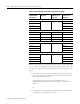
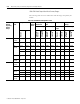
Table 4.9 and Table 4.10 describes how ramp rate is defined for all output
range/types and output data formats.
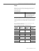
Table 4.8 Ramping Types
Ramping Type Description
Ramp to Fault Mode This type of ramping occurs when the
present output value changes to the Fault
Value after a communications fault occurs.
This is the only type of ramping for the
1769-OF4CI and -OF4VI modules.
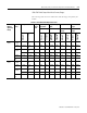
Table 4.9 1769-OF4CI Output Range/Types and Output Data Formats
Output Data
Format Output
Range/Type
Total Counts in
Full Scale
Number of Counts
for Every 1% of
Ramp Rate
Real Units/Second
for Every 1% of
Ramp Rate
Proportional Counts
0…20 mA 65534 655 0.2 mA/s
4…20 mA 0.16 mA/s
Engineering Units
0…20 mA 21000 210 0.2 mA/s
4…20 mA 17800 178 0.16 mA/s
Scaled for PID
0…20 mA 16383 164 0.2 mA/s
4…20 mA 0.16 mA/s
Percent of Full Scale
0…20 mA 10000 100 0.2 mA/s
4…20 mA 0.16 mA/s