
Manual

Publication 1769-UM014B-EN-P - May 2010
Module Data, Status, and Channel Configuration for the Output Modules 4-3
1769-OF4CI and -OF4VI
Output Data File
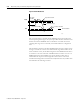
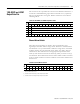
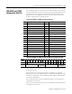
The structure of the output data file is shown in the table below. Words 0 to 3
contain the commanded analog output data for channels 0 to 3, respectively.
The most significant bit is the sign bit. Word 4 contains the control bits for
unlatching alarms.
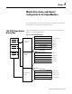
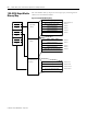
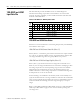
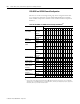
Channel Alarm Unlatch
These bits are written during run mode to clear any latched low- and
high-clamps and under- and over-range alarms. The alarm is unlatched when
the unlatch bit is set (1) and the alarm condition no longer exists. If the alarm
condition persists, then the unlatch bit has no effect. You need to keep the
unlatch bit set until verification from the appropriate input channel status
word says that the alarm status bit has cleared (0). Then you need to reset (0)
the unlatch bit. The module will not latch an alarm condition when a transition
from a no alarm condition to an alarm condition occurs while a channel’s clear
latch bit is set.
Table 4.1 1769-OF4CI and -OF4VI Output Data Table
Word
Bit Position
1514131211109876543210
0 SGN Analog Output Data Channel 0
1 SGN Analog Output Data Channel 1
2 SGN Analog Output Data Channel 2
3 SGN Analog Output Data Channel 3
4 UU3 UO3 UU2 UO2 UU1 UO1 UU0 UO0
Table 4.2 Channel Alarm Unlatch
Word
Bit Position
15 14 13 12 11 10 9 8 7 6 5 4 3 2 1 0
0
Nu
(1)
Nu Nu Nu Nu Nu Nu Nu
UU3
(2)
UO3
(3)
UU2 UO2 UU1 UO1 UU0 UO0
(1)
Not used. Bit must be set to 0.
(2)
Unlatch channel x under-range or low-clamp exceeded alarm.
(3)
Unlatch channel x over-range or high-clamp exceeded alarm.