
Manual

Publication 1769-UM014B-EN-P - May 2010
Module Data, Status, and Channel Configuration for the Input Module 3-3
1769-IF4I Input Data File
The input data table lets you access analog input module read data for use in
the control program, via word and bit access. The data table structure is shown
in the table below. For each input module, slot x, words 0 to 3 in the input data
file contain the analog values of the inputs.
1769-IF4I Input Data Values
Words 0 to 3 contain the converted analog input data from the field device.
The most significant bit (MSB) is the sign bit, which is in two’s complement
format. (Nu indicates not used with the bit set to 0.)
General Status Bits (S0 to S3)
Word 5, bits 0 to 3 contain the general operational status bits for input
channels 0 to 3. If set (1), these bits indicate an error associated with that
channel. The over- and under-range bits and the high- and low-alarm bits for
channels 0 to 3 are logically ORed to the appropriate general status bit.
Low Alarm Flag Bits (L0 to L3)
Word 6, bits 3, 7, 11, and 15 contain the low alarm flag bits for input channels
0 to 3. If set (1), these bits indicate the input signal is outside the user-defined
range. The module continues to convert analog data to minimum full-range
values. The bit is automatically reset (0) when the low alarm condition clears,
unless the channel’s alarm bits are latched. If the channel’s alarm bits are
latched, a set (1) low alarm flag bit clears via the corresponding Clear Alarm
Latch bit in your output data file.
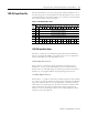
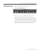
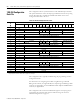
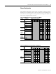
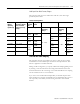
Table 3.1 1769-IF4I Input Data Table
Word
Bit Position
1514131211109876543210
0 SGN Analog Input Data Channel 0
1 SGN Analog Input Data Channel 1
2 SGN Analog Input Data Channel 2
3 SGN Analog Input Data Channel 3
4 Nu Time Stamp Value
5 Nu NuNuNuNuNuNuNuNuNuNuNuS3S2S1 S0
6 L3 H3U3O3L2H2U2O2L1H1U1O1L0H0U0O0