
Manual

1 Publication 1769-UM014B-EN-P - May 2010
Chapter
3
Module Data, Status, and Channel
Configuration for the Input Module
This chapter examines the analog input module’s data table, channel status, and
channel configuration word.
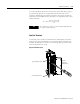
1769-IF4I Input Module
Addressing
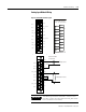
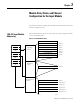
The1769-IF4I memory map shows the output, input, and configuration tables
for the 1769-IF4I module.
Figure 3.1 1769-IF4I Memory Map
Slot e
Input Image
File
Output Image
File
Configuration
File
Slot e
Slot e
Input Image
7 Words
Output Image
1 Word
Configuration File
26 Words
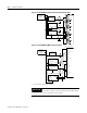
Memory Map
Bit 15 Bit 0
Channel 3 Configuration Words Words 20 to 25
Channel 2 Configuration Words Words 14 to 19
Channel 1 Configuration Words Words 8 to 13
Channel 0 Configuration Words Words 2 to 7
Clear Latched Alarm Bits Word 0
High-/Low-alarm & Over-/Under-range Word 6
General Status Bits Word 5
Time Stamp Value Word Word 4
Channel 3 Data Word Word 3
Word 2Channel 2 Data Word
Word 1Channel 1 Data Word
Channel 0 Data Word Word 0
Enable Time Stamp Word 1, bit 15
Real Time Sample Rate Word 0