
Manual

Publication 1769-UM014B-EN-P - May 2010
Installation and Wiring 2-19
Analog Input Module Wiring
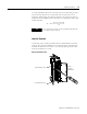
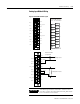
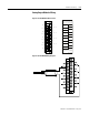
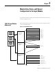
Figure 2.9 1769-IF4I Terminal Layout
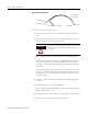
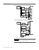
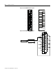
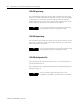
Figure 2.10 1769-IF4I Wiring Differential Inputs
N/C
N/C
Ch2-
Ch2_iRtn
Ch2+
N/C
Ch0-
Ch0_iRtn
Ch0+
Ch3-
Ch3_iRtn
Ch3+
N/C
Ch1-
Ch1_iRtn
Ch1+
N/C
N/C
Ch2+
Ch1-
Ch1+
Ch1_iRtn
Ch3-
Ch3+
Ch3_iRtn
N/C
N/C
N/C
Ch0+
N/C
N/C
Ch2-
Ch2_iRtn
N/C
Ch0-
Ch0_iRtn
W ARNING -Do Not
Remove RTB Unless
Area is Non-Hazar
1769-IF4I
Belden 8761 Cable
(or equivalent)
Analog Voltage Source
Analog Current Source
N/C
N/C
N/C
N/C
N/C
N/C
Ch1+
Ch2+
Ch0+
Ch3+
Ch1-
Ch2-
Ch0-
Ch3-
Ch1_iRtn
Ch2_iRtn
Ch0_iRtn
Ch3_iRtn
IMPORTANT
1769-IF4I input channels connected to current sources
must have a jumper wire placed between Ch#_iRtn and the
Ch#- terminals for that channel.